IBM System x3400 M3 Types 7378 Скачать руководство пользователя страница 102

Table 9. Memory-mirroring mode DIMM population sequence (continued)

DIMMs

Number of installed
microprocessors

DIMM connector

Second pair of DIMMs

1

2, 5

Third pair of DIMMs

1

1, 4

Fourth pair of DIMMs

2

14, 11

Fifth pair of DIMMs

2

13, 10

Sixth pair of DIMMs

2

12, 9

Note:

DIMM connectors 7, 8, 15, and 16 are not used in memory-mirroring mode.

When you install or remove DIMMs, the server configuration information changes.
When you restart the server, the system displays a message that indicates that the
memory configuration has changed.

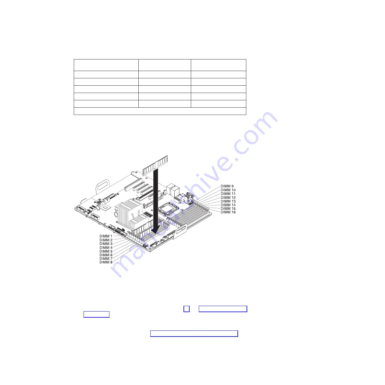
The following illustration shows how to install DIMMs on the system board.

Attention:

Static electricity that is released to internal server components when

the server is powered-on might cause the server to stop, which might result in the
loss of data. To avoid this potential problem, always use an electrostatic-discharge
wrist strap or other grounding system when you work inside the server with the
power on.

To install a DIMM, complete the following steps:

1. Read the safety information that begins on page vii and “Installation guidelines”

on page 29.

2. Turn off the server and peripheral devices; then, disconnect the power cords

and all external cables.

3. Remove the left-side cover (see “Removing the left-side cover” on page 49).

4. Remove the hot-swap power supply or power supplies from the server.

86

IBM System x3400 M3 Types 7378 and 7379: Installation and User's Guide

Содержание System x3400 M3 Types 7378

Страница 1: ...IBM System x3400 M3 Types 7378 and 7379 Installation and User s Guide...

Страница 2: ......

Страница 3: ...IBM System x3400 M3 Types 7378 and 7379 Installation and User s Guide...

Страница 4: ...afety Information Environmental Notices and User Guide documents on the IBM Documentation CD and the Warranty Information document that comes with the server Ninth Edition February 2012 Copyright IBM...

Страница 5: ...AS backplane connectors 27 Operator information panel 28 Installation guidelines 29 System reliability guidelines 30 Working inside the server with the power on 30 Handling static sensitive devices 31...

Страница 6: ...14 Enabling the Broadcom Gigabit Ethernet Utility program 115 Configuring the Gigabit Ethernet controller 115 Using the LSI Configuration Utility program 116 Starting the LSI Configuration Utility pro...

Страница 7: ...Industries Association JEITA statement 128 Korean Class A warning statement 128 Russia Electromagnetic Interference EMI Class A statement 129 People s Republic of China Class A electronic emission sta...

Страница 8: ...vi IBM System x3400 M3 Types 7378 and 7379 Installation and User s Guide...

Страница 9: ...en Ennen kuin asennat t m n tuotteen lue turvaohjeet kohdasta Safety Information Avant d installer ce produit lisez les consignes de s curit Vor der Installation dieses Produkts die Sicherheitshinweis...

Страница 10: ...ons of the caution or danger statement in the IBM Safety Information document For example if a caution statement is labeled Statement 1 translations for that caution statement are in the Safety Inform...

Страница 11: ...quipment when there is evidence of fire water or structural damage v Disconnect the attached power cords telecommunications systems networks and modems before you open the device covers unless instruc...

Страница 12: ...ttery replace it only with the same module type made by the same manufacturer The battery contains lithium and can explode if not properly used handled or disposed of Do not v Throw or immerse into wa...

Страница 13: ...he device v Use of controls or adjustments or performance of procedures other than those specified herein might result in hazardous radiation exposure DANGER Some laser products contain an embedded Cl...

Страница 14: ...ce and the power switch on the power supply do not turn off the electrical current supplied to the device The device also might have more than one power cord To remove all electrical current from the...

Страница 15: ...inside any component that has this label attached There are no serviceable parts inside these components If you suspect a problem with one of these parts contact a service technician Statement 11 CAUT...

Страница 16: ...cifications Statement 15 CAUTION Make sure that the rack is secured properly to avoid tipping when the server unit is extended Statement 17 CAUTION The following label indicates moving parts nearby St...

Страница 17: ...y and serviceability on page 12 You can obtain up to date information about the server and other IBM server products at http www ibm com systems x At http www ibm com support mysupport you can create...

Страница 18: ..._____ The model number and serial number are on labels on the bottom of the server and on the front visible through the bezel as shown in the following illustration Important The server keys cannot be...

Страница 19: ...e than one document press and hold the Ctrl key while you select the documents Click View Book to view the selected document or documents in Acrobat Reader or xpdf If you selected more than one docume...

Страница 20: ...pdated occasionally to include information about those features or technical updates might be available to provide additional information that is not included in the server documentation These updates...

Страница 21: ...iption of a potentially hazardous procedure step or situation v Danger These statements indicate situations that can be potentially lethal or extremely hazardous to you A danger statement is placed ju...

Страница 22: ...d in the server before you run DSA from a bootable CD v Maximum 128 GB 48 GB using unbuffered DIMMs UDIMMs 128 GB using registered DIMMs RDIMMs v Type Registered or unbuffered ECC double data rate 3 D...

Страница 23: ...niversal Serial Bus USB ports standard v2 0 supporting v1 1 Four on rear of server Two on front of server v One internal USB tape connector v One Broadcom dual port 10 100 1000 Ethernet controller wit...

Страница 24: ...onal features that are installed and the power management optional features that are in use 2 These levels were measured in controlled acoustical environments according to the procedures that are spec...

Страница 25: ...IMM provides remote server management through industry standard interfaces Intelligent Platform Management Interface IPMI version 2 0 Simple Network Management Protocol SNMP version 3 Common Informati...

Страница 26: ...ide Setup and Installation CD see Using the ServerGuide Setup and Installation CD on page 109 v IBM X Architecture technology IBM X Architecture technology combines proven innovative IBM designs to ma...

Страница 27: ...ing on your model 2 5 inch or eight 3 5 inch hard disk drives in the hot swap bays With the hot swap feature you can add remove or replace hard disk drives without turning off the server Note SAS expa...

Страница 28: ...e and correct problems The server has the following RAS features v 3 year parts 3 year labor limited warranty 1 year warranty is available in limited geography v Advanced Configuration and Power Inter...

Страница 29: ...forms Through a single user interface IBM Systems Director provides consistent views for viewing managed systems determining how these systems relate to one another and identifying their statuses help...

Страница 30: ...pdates For additional information and to download the UpdateXpress System Pack Installer go to the System x and BladeCenter Tools Center at http publib boulder ibm com infocenter toolsctr v1r0 index j...

Страница 31: ...the system board might also be lit to help isolate the error USB connectors Connect USB devices to these connectors DVD eject button Press this button to release a CD or DVD from the DVD drive DVD dr...

Страница 32: ...eceive activity LED Ethernet link status LED AC power LED DC power LED Fault error LED Power cord connector Connect the power cord to this connector AC power LED This green LED provides status informa...

Страница 33: ...he IMM through a single network cable Ethernet transmit receive activity LED This LED is on the Ethernet connector When this LED is lit it indicates that there is activity between the server and the n...

Страница 34: ...oviding power to the server Off On Off Faulty power supply Replace the power supply Off On On Faulty power supply Replace the power supply On Off Off Power supply not fully seated faulty system board...

Страница 35: ...r is connected to an AC power source but is not turned on the operating system does not run and all core logic except for the integrated management module IMM is shut down however the server can respo...

Страница 36: ...ff the server See your operating system documentation for information about shutting down the operating system Statement 5 CAUTION The power control button on the device and the power switch on the po...

Страница 37: ...Guide for information about how to run diagnostics 3 Follow the installation procedures in this chapter and use the correct tools Incorrectly installed devices can cause system failures because of da...

Страница 38: ...rver open or close a latch and so on Orange on a component or an orange label on or near a component indicates that the component can be hot swapped which means that if the server and operating system...

Страница 39: ...on the system board The following illustration shows the additional PCI Express expansion slot that is available on the PCI Express extender card The following illustration shows two additional PCI X...

Страница 40: ...serted by default The physical presence needs to be asserted to activate deactivate clear or change ownership of the TPM Note If no jumper is present the server responds as on default position Table 5...

Страница 41: ...illustration shows the LEDs on the system board System board external connectors The following illustration shows the external input output connectors and the NMI button on the system board Chapter 2...

Страница 42: ...26 IBM System x3400 M3 Types 7378 and 7379 Installation and User s Guide...

Страница 43: ...kplane connectors The following illustrations show the connectors on the SAS backplanes Figure 1 3 5 inch backplane connectors Figure 2 2 5 inch backplane connectors Chapter 2 Installing optional devi...

Страница 44: ...cond The server is turned off and is not ready to be turned on The power control button is disabled This will last approximately 20 to 40 seconds Note Approximately 20 seconds after the server is conn...

Страница 45: ...r is not working correctly see the Problem Determination and Service Guide on the IBM Documentation CD for information about how to run diagnostics v Observe good housekeeping in the area where you ar...

Страница 46: ...llowed the cabling instructions that come with optional adapters v You have replaced a failed fan within 48 hours v You have replaced a hot swap drive within 2 minutes of removal v You have replaced a...

Страница 47: ...ully holding it by its edges or its frame v Do not touch solder joints pins or exposed circuitry v Do not leave the device where others can handle and damage it v While the device is still in its stat...

Страница 48: ...es attached If you replace any drives remember which cable is attached to which drive v When you route a cable make sure that it does not block the airflow to the rear of the drives or over the microp...

Страница 49: ...raditional power converter cable when you install an RDX internal USB tape drive in the server This cable comes with the server in the plastic bag with the drive rails Connects to tape drive Connects...

Страница 50: ...Power converter cable Optical power cable SATA connector Tape drive 34 IBM System x3400 M3 Types 7378 and 7379 Installation and User s Guide...

Страница 51: ...disconnect the cable by using excessive force Failing to remove the cable properly may damage the connectors on the system board Any damage to the connectors may require replacing the system board The...

Страница 52: ...he chassis then pull to remove the cable from the connector on the system board Pulling the cable out of the connector by excessive force might cause damage to the cable or connector 2 To connect the...

Страница 53: ...Chapter 2 Installing optional devices 37...

Страница 54: ...rnal drives 1 The following illustrations show the connectors on the 2 5 inch and 3 5 inch hard disk drive backplanes Figure 3 Connectors on the 3 5 inch hard disk drive backplane Figure 4 Connectors...

Страница 55: ...he slot next in sequence to a ServeRAID adapter with battery backup module for example if a ServeRAID adapter with battery backup module is installed in slot 2 do not install any card in slot 3 Figure...

Страница 56: ...t have to reconfigure your disk arrays after you install drives See the ServeRAID adapter documentation for additional information about RAID operation and complete instructions for using the ServeRAI...

Страница 57: ...four 3 5 inch hot swap hard disk drives v The following illustration shows the internal power cable routing v The following illustration shows the internal configuration cable routing v The following...

Страница 58: ...42 IBM System x3400 M3 Types 7378 and 7379 Installation and User s Guide...

Страница 59: ...wing illustration shows the internal power cable routing v The following illustration shows the internal configuration cable routing v The following illustration shows the internal signal cable routin...

Страница 60: ...44 IBM System x3400 M3 Types 7378 and 7379 Installation and User s Guide...

Страница 61: ...wing illustration shows the internal power cable routing v The following illustration shows the internal configuration cable routing v The following illustration shows the internal signal cable routin...

Страница 62: ...46 IBM System x3400 M3 Types 7378 and 7379 Installation and User s Guide...

Страница 63: ...ixteen 2 5 inch hot swap hard disk drives v The following illustration shows the internal power cable routing v The following illustration shows the internal configuration cable routing Chapter 2 Inst...

Страница 64: ...the internal signal cable routing for installing a ServeRAID adapter and a ServeRAID expansion adapter Note SAS expander card does not support 3 GB RAID adapters 48 IBM System x3400 M3 Types 7378 and...

Страница 65: ...that begins on page vii and Installation guidelines on page 29 2 If you are planning to view the error LEDs that are on the system board and components leave the server connected to power and go direc...

Страница 66: ...r remove the bezel When you lock the left side cover it locks both the cover and the bezel 3 Press the button on the left edge of the bezel and rotate the left side of the bezel away from the server 4...

Страница 67: ...m the bezel push upward on the media door hinge to remove it from the bezel 5 When the media door is unlocked the icon on the side of the bezel will be in the unlocked position Media door icon Chapter...

Страница 68: ...ds 4 Remove the left side cover see Removing the left side cover on page 49 for more information 5 Remove the power supplies from the power supply cage 6 Unlatch the power supply cage and rotate it ou...

Страница 69: ...ge to its closed position see Closing the power supply cage on page 56 5 Install the hot swap power supply or power supplies see Installing a redundant power supply on page 98 6 Install and lock the l...

Страница 70: ...n place 3 Install the air baffle see Installing the air baffle on page 53 4 Rotate the power supply cage assembly back into the server Press the power supply release tab and rotate the power supply ca...

Страница 71: ...ernal cables 3 Press the release latch on the power supplies and pull them out of the power supply cage Hot swap power supply Release latch 4 Unlock and remove the left side cover see Removing the lef...

Страница 72: ...t bracket Power supply support bracket Power supply release tab Attention Be sure to move the cables out of the way of the power supply cage before you start to move the cage back into the server 2 Ca...

Страница 73: ...ngages the notch in the front latch bracket then lower the handle until it locks in place Power supply cage closed 4 Install and lock the left side cover see Completing the installation on page 98 5 I...

Страница 74: ...compliant Slot 6 is a PCI 33 32 slot PCI 2 2 compliant PCI Express extender card slot 7 is a PCI Express x8 slot with x4 links PCI Express 1 0a compliant Note The PCI Express extender card comes stand...

Страница 75: ...e documentation that comes with the adapter for any cabling instructions and information about jumper or switch settings It might be easier for you to route cables before you install the adapter 4 Rot...

Страница 76: ...closed position Attention Incomplete insertion might cause damage to the system board or the adapter 8 Connect any needed cables to the adapter If you have other devices to install or remove do so now...

Страница 77: ...stallation guidelines on page 29 b Turn off the server and peripheral devices and disconnect the power cords and all external cables c Unlock and remove the left side cover see Removing the left side...

Страница 78: ...from the bay in which you want to install the drive Note If you are installing a drive that contains a laser observe the following safety precaution 62 IBM System x3400 M3 Types 7378 and 7379 Install...

Страница 79: ...l instruments and avoid direct exposure to the beam Class 1 Laser Product Laser Klasse 1 Laser Klass 1 Luokan 1 Laserlaite Appareil A Laser de Classe 1 g Touch the static protective package that conta...

Страница 80: ...d Internal cable routing and connectors on page 32 for more information l Route the signal cable through the plastic slot on the bottom of the chassis underneath the fan cage assembly so that it does...

Страница 81: ...n the documentation that comes with the new drive v You have checked the instructions that come with the new drive to determine whether you must set any switches or jumpers in the drive v You have rem...

Страница 82: ...e to any unpainted metal surface on the server then remove the UltraSlim DVD drive from the package c Read the safety information that begins on page vii and Installation guidelines on page 29 d Turn...

Страница 83: ...bly all the way up until the retainer latch locks the cage in place on the chassis i Disconnect the power and signal cables of the DVD drive from the system board j Pull the power and signal cables of...

Страница 84: ...signal cables of the UltraSlim DVD drive into the slim slot on top of the cage first Make sure the cables are not stuck when you slide the UltraSlim DVD drive into the cage n Slide the 3 5 inch disk d...

Страница 85: ...and connectors on page 32 for more information q Reinstall the air baffle r Reinstall the fan cage assembly s Rotate the power supply cage assembly back into the server Press the power supply cage re...

Страница 86: ...ds then turn on the attached devices and turn on the server If you have other devices to install or remove do so now Otherwise go to Completing the installation on page 98 70 IBM System x3400 M3 Types...

Страница 87: ...he safety information that begins on page vii and Installation guidelines on page 29 2 Turn off the server and peripheral devices and disconnect the power cords and all external cables 3 Unlock and re...

Страница 88: ...zel 9 Remove the power supplies from the rear of the server 10 Carefully lay the server down on its side 11 Open the power supply cage see Opening the power supply cage on page 55 for more information...

Страница 89: ...of the cable to the back of the tape drive see Internal cable routing and connectors on page 32 for more information Note If you are installing an RDX internal USB tape drive use the SATA to traditio...

Страница 90: ...for more information 20 Reinstall the power supplies 21 Replace the left side cover then lock the left side cover and bezel 22 Reconnect the external cables and power cords If you have other devices t...

Страница 91: ...ww ibm com servers eserver serverproven compat us v Inspect the drive tray for signs of damage v Make sure that the drive is correctly installed in the tray v See the documentation for the ServeRAID a...

Страница 92: ...e amber hard disk drive status LED is lit continuously that drive is faulty and must be replaced If the green hard disk drive activity LED is flashing the drive is being accessed 2 If the server is co...

Страница 93: ...left bay bay 4 and go the right bay bay 7 in that order To install a simple swap hard disk drive complete the following steps 1 Read the safety information that begins on page vii and Installation gu...

Страница 94: ...ve bay until it stops and release the loops Note Do not release the loops on the drive assembly until it is completely seated 10 See the Problem Determination and Service Guide for cabling information...

Страница 95: ...icroprocessor improves server performance v When two microprocessors are installed in the server distribute the DIMMs between the two microprocessors to improve server performance v The server support...

Страница 96: ...V The following notes describe the types of DIMMs that the server supports and other information that you must consider when you install DIMMs v When you install or remove DIMMs the server configurat...

Страница 97: ...e combination of the microprocessor DIMM speed and the number of DIMMs installed in each channel v In two DIMM per channel configuration a server with an Intel Xeon X5600 series microprocessor automat...

Страница 98: ...using UDIMMs Note The amount of usable memory is reduced depending on the system configuration A certain amount of memory must be reserved for system resources To view the total amount of installed me...

Страница 99: ...adapters that you removed 3 Close the rear adapter retention bracket 4 Install and lock the left side cover see Completing the installation on page 98 5 Lock the left side cover 6 Reconnect the extern...

Страница 100: ...ry mirroring see Using the Setup utility on page 102 When you use the memory mirroring feature consider the following information v When you use memory mirroring you must install a pair of DIMMs at a...

Страница 101: ...processor 1 socket CPU1 The numbers within the boxes indicate the installation sequence of the DIMM pairs For example the first DIMM pair indicated within the boxes by 1s should be installed in DIMM c...

Страница 102: ...oard Attention Static electricity that is released to internal server components when the server is powered on might cause the server to stop which might result in the loss of data To avoid this poten...

Страница 103: ...is a gap between the DIMM and the retaining clips the DIMM has not been correctly inserted open the retaining clips remove the DIMM and then reinsert it 11 Reinstall the air baffle see Installing the...

Страница 104: ...DIMMs 1 2 5 7 3rd set of DIMMs 2 11 14 16 4th set of DIMMs 2 10 13 15 Notes 1 The 3rd and 4th sets of DIMMs can be installed right after microprocessor 2 is installed even 1st and 2nd sets of DIMM slo...

Страница 105: ...6 Close the rear adapter retention bracket 7 Install and lock the left side cover see Completing the installation on page 98 Chapter 2 Installing optional devices 89...

Страница 106: ...he flash device with the USB connector on the system board and push it into the USB connector until it is firmly seated 6 Return the retention latch to the locked position by pulling it away from the...

Страница 107: ...e the following steps 1 Go to http www ibm com systems support 2 Under Product support click System x 3 Under Popular links click Software and device drivers 4 Click System x3400 M3 to display the mat...

Страница 108: ...rds and all external cables Remove the left side cover see Removing the left side cover on page 49 for more information 3 Remove the hot swap power supplies from the server 4 Open the power supply cag...

Страница 109: ...rocessor into the socket d Make sure that the microprocessor is oriented aligned and positioned in the socket before you try to close the lever 9 Install the microprocessor a Touch the static protecti...

Страница 110: ...he microprocessor in the tool Note You can pick up or release the microprocessor by twisting the microprocessor installation tool handle Installation tool Handle g Carefully align the microprocessor i...

Страница 111: ...stallation tool Handle 10 Close the microprocessor bracket frame then close the microprocessor retention latch and lock it securely in place Microprocessor bracket frame Microprocessor retention latch...

Страница 112: ...sition b Remove the plastic protective cover from the bottom of the heat sink c Align the heat sink above the microprocessor using the alignment key on the heat sink with the thermal grease side down...

Страница 113: ...pressure on both ends of the VRM simultaneously The retaining clips snap into the locked position when the VRM is seated in the connector 14 Reinstall the air baffle see Installing the air baffle on p...

Страница 114: ...he other end of the power cord to a properly grounded electrical outlet 6 Make sure that the AC power LED on the top of each power supply is lit indicating that the power supply is operating correctly...

Страница 115: ...dditional cabling instructions see the documentation that comes with the optional devices It might be easier for you to route any cables before you install certain optional devices 3 Cable identifiers...

Страница 116: ...have device drivers that you must install For information about installing device drivers see the documentation that comes with each device The server comes with at least one microprocessor If more t...

Страница 117: ...Using the integrated management module on page 111 and the IMM User s Guide on the IBM Web Site v Remote presence capability and blue screen capture The remote presence and blue screen capture featur...

Страница 118: ...ager MSM Director ServeRAID M5014 adapter LSI SAS2108 MegaRAID BIOS Configuration Utility ServerGuide MegaRAID Storage Manager MSM Director ServeRAID M5015 adapter LSI SAS2108 MegaRAID BIOS Configurat...

Страница 119: ...tly in the system information This choice is on the full Setup utility menu only System Summary Select this choice to view configuration information including the ID speed and cache size of the microp...

Страница 120: ...ce to view or change power capping to control consumption processors and performance states Legacy Support Select this choice to view or set legacy support Force Legacy Video on Boot Select this choic...

Страница 121: ...vers Select this choice to view information about the adapters and device drivers in the server that are compliant with EFI 1 10 and UEFI 2 0 v Network Select this choice to view or configure the netw...

Страница 122: ...t or change a power on password For more information see Power on password on page 107 Clear Power on Password Select this choice to clear a power on password For more information see Power on passwor...

Страница 123: ...ator password to access the Setup utility menu If you set a power on password for a user and an administrator password for a system administrator you can type either password to complete the system st...

Страница 124: ...he power on password override You can then start the Setup utility and reset the power on password You do not have to return the switch to the previous position The power on password override jumper d...

Страница 125: ...is restored turn off the server then move the UEFI boot recovery JP6 jumper back to the primary position pins 1 and 2 Using the ServerGuide Setup and Installation CD The ServerGuide Setup and Installa...

Страница 126: ...stallation Setup and configuration overview When you use the ServerGuide Setup and Installation CD you do not need setup diskettes You can use the CD to configure any supported IBM server model The se...

Страница 127: ...n program for the operating system takes control to complete the installation Installing your operating system without using ServerGuide If you have already configured the server hardware and you are...

Страница 128: ...disk drives and system errors v NMI detection and reporting v Operating system failure blue screen capture v PCI configuration data v PECI 2 support v Power reset control power on hard and soft shutdo...

Страница 129: ...Enter 6 Select Save Settings and then select Exit Setup If the embedded hypervisor flash device image becomes corrupt you can use the VMware Recovery CD that comes with the system to recover the flas...

Страница 130: ...eps 1 Turn on the server Note Approximately 20 seconds after the server is connected to AC power the power control button becomes active 2 When the prompt F1 Setup is displayed press F1 If you have se...

Страница 131: ...teps 1 From the Setup utility main menu select Devices and I O Ports and press Enter 2 Select Enable Disable onboard device s and press Enter 3 Select Ethernet and press Enter 4 Select Enable and pres...

Страница 132: ...to create an integrated array of two disks All data on the primary disk can be migrated Integrated Mirroring Enhanced IME with hot spare support also known as RAID 1E Use this option to create an inte...

Страница 133: ...this procedure Note Before you format a hard disk make sure that the disk is not part of a mirrored pair To format a drive complete the following steps 1 From the list of adapters select the controlle...

Страница 134: ...ightly from what is described in this document To locate and install a newer version of IBM Systems Director complete the following steps 1 Check for the latest version of IBM Systems Director a Go to...

Страница 135: ...server on the Welcome page of the IBM Systems Director Web interface click the Manage tab and click Update Manager 9 Click Import updates and specify the location of the downloaded files that you copi...

Страница 136: ...120 IBM System x3400 M3 Types 7378 and 7379 Installation and User s Guide...

Страница 137: ...gnostic tests that you can perform Most systems operating systems and programs come with documentation that contains troubleshooting procedures and explanations of error messages and error codes If yo...

Страница 138: ...U S and Canada call 1 800 IBM SERV 1 800 426 7378 Hardware service and support You can receive hardware service through your IBM reseller or IBM Services To locate a reseller authorized by IBM to pro...

Страница 139: ...FOR A PARTICULAR PURPOSE Some states do not allow disclaimer of express or implied warranties in certain transactions therefore this statement may not apply to you This information could include techn...

Страница 140: ...volume KB stands for 1024 bytes MB stands for 1 048 576 bytes and GB stands for 1 073 741 824 bytes When referring to hard disk drive capacity or communications volume MB stands for 1 000 000 bytes an...

Страница 141: ...Limits Particulate v The room air must be continuously filtered with 40 atmospheric dust spot efficiency MERV 9 according to ASHRAE Standard 52 21 v Air that enters a data center must be filtered to 9...

Страница 142: ...to radio communications Operation of this equipment in a residential area is likely to cause harmful interference in which case the user will be required to correct the interference at his own expense...

Страница 143: ...kt entspricht den Schutzanforderungen der EU Richtlinie 2004 108 EG zur Angleichung der Rechtsvorschriften ber die elektromagnetische Vertr glichkeit in den EU Mitgliedsstaaten und h lt die Grenzwerte...

Страница 144: ...hningen Germany Telephone 49 7032 15 2937 Email tjahn de ibm com Generelle Informationen Das Ger t erf llt die Schutzanforderungen nach EN 55024 und EN 55022 Klasse A VCCI Class A statement This is a...

Страница 145: ...Russia Electromagnetic Interference EMI Class A statement People s Republic of China Class A electronic emission statement Taiwan Class A compliance statement Appendix B Notices 129...

Страница 146: ...130 IBM System x3400 M3 Types 7378 and 7379 Installation and User s Guide...

Страница 147: ...dating server 101 with ServerGuide 110 configuration programs LSI Configuration Utility 102 connecting the cables 99 connector Ethernet 17 power cord 16 serial 1 16 video 16 connector systems manageme...

Страница 148: ...order of installation 77 simple swap 77 types and installation information 75 hardware service and support 122 heat output 8 heat sink 95 help getting 121 hot swap drive backplane SAS SATA IDs 78 hot...

Страница 149: ...ce 85 88 memory module installing 79 order of installation 86 memory sparing description 87 memory sparing mode 87 menu choices in Setup utility 103 microprocessor 6 12 heat sink 95 installation 92 ty...

Страница 150: ...ment SATA simple swap drives 77 Serial Attached SCSI SAS SATA backplane IDs for hot swap drives 78 server components 22 configuration updating 101 firmware starting backup 109 firmware UEFI compliant...

Страница 151: ...s A notice 126 United States FCC Class A notice 126 UpdateXpress 14 updating IBM Systems Director 118 server configuration 100 101 USB connectors front 15 rear 17 USB or SATA tape drive 71 user securi...

Страница 152: ...136 IBM System x3400 M3 Types 7378 and 7379 Installation and User s Guide...

Страница 153: ......

Страница 154: ...Part Number 00D3189 Printed in USA 1P P N 00D3189...

Отзывы: