Procedure
1. Check for any non-IBM changes that were made to the device. If any are present, obtain the “Non-IBM
Alteration Attachment Survey,” form number R009, from the IBM branch office. Complete the form
and return it to the branch office.
2. Check the condition of the inside of the device for any metal or other contaminants, or any indications
of water, other fluid, fire, or smoke damage.
3. Check for any obvious mechanical problems, such as loose components.
4. Check any exposed cables and connectors for wear, cracks, or pinching.
Checking the grounding of the system and redundant AC-power switch
Ensure that you understand how to check the grounding of a system and the optional redundant AC-
power switch feature.
About this task
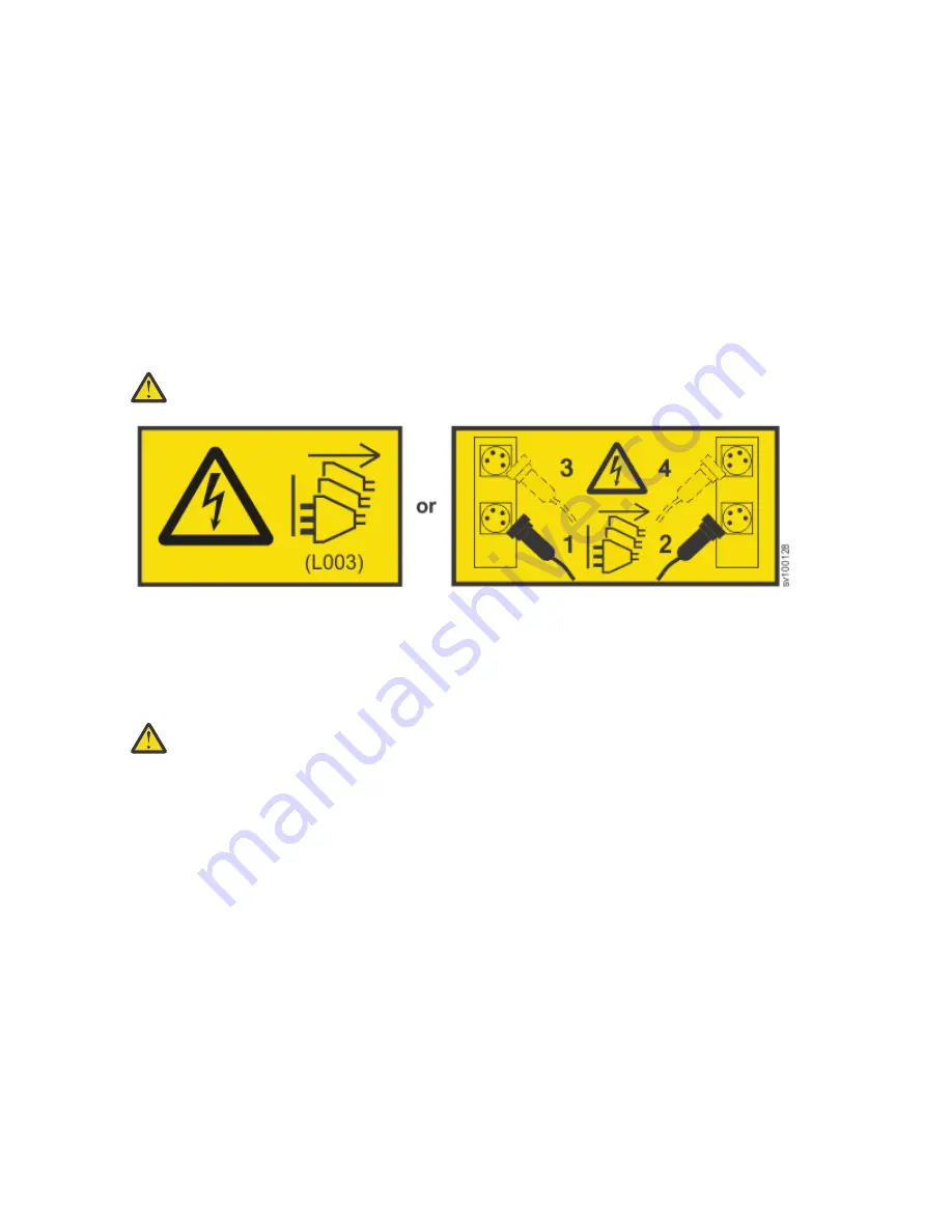
DANGER: Multiple power cords. The product might be equipped with multiple power cords. To
remove all hazardous voltages, disconnect all power cords. (L003)
To test the grounding of a system node, follow the steps for the specific system configuration that you are
using. Before you start, confirm that you know the model type of your system, and whether you are using
redundant AC power. Determine the location of the signal cables that are attached to the system.
When you are asked to test the grounding continuity, use your local procedures to initiate the test. The
test is successful if the measured resistance is 0.1 ohm or less.
Attention: Some electrical circuits can be damaged if the external signal cables are present at the
node while it is undergoing a grounding test.
Procedure
1. Ensure that the node is powered off. See MAP 5350: Powering off a SAN Volume Controller node in the
IBM SAN Volume Controller Troubleshooting Guide.
2. Disconnect all signal cables from the node, which includes the following cables:
• The Fibre Channel cables.
• The Ethernet cable or cables.
3. If redundant AC power is used, turn off any node that is being supplied from the redundant AC-power
switch. Then, remove the power cable to this system from the redundant AC-power switch.
4. Disconnect both input power leads from the site power distribution units
5. If redundant AC power is used, test the grounding continuity between a conductive area on the frame
and the ground pin on the plug of the main power cable of the redundant AC-power switch. If the test
is successful, test the grounding continuity between a conductive area on the frame and the ground
pin on the plug of the backup power cable of the redundant AC-power switch. Both tests must be
successful.
6. Initiate one of the following procedures after you complete testing the grounding continuity,
depending on the outcome of the test.
• If the test is successful, reconnect any cables that were removed.
Safety and environmental notices xv
Содержание SAN Volume Controller 2145
Страница 1: ...SAN Volume Controller 8 3 1 Quick Start Guide Machine Types 2145 2147 Models SA2 SV2 IBM...
Страница 4: ...iv...
Страница 6: ...vi SAN Volume Controller 8 3 1 Machine Types 2145 2147 Models SA2 SV2...
Страница 32: ...12 SAN Volume Controller 8 3 1 Machine Types 2145 2147 Models SA2 SV2...
Страница 42: ...22 SAN Volume Controller 8 3 1 Machine Types 2145 2147 Models SA2 SV2...
Страница 44: ...24 SAN Volume Controller 8 3 1 Machine Types 2145 2147 Models SA2 SV2...
Страница 45: ......
Страница 46: ...IBM Part Number 03GH323 1P P N 03GH323...


