296
RS/6000 SP and Clustered IBM
^
pSeries Systems Handbook
In configuration (c) of Figure 10-6 on page 295, there are eight Wide nodes
mounted in a tall model frame equipped with an SP Switch and four High nodes
mounted in a non-switched expansion frame (Frame 2). The second
non-switched expansion frame (Frame 3) is housed in a High node, two Wide
nodes, and one PCI Thin node. This configuration occupies all 16 switch ports in
the model frame. Note that Wide nodes and PCI Thin nodes in Frame 3 have to
be placed in the location that is similar to a high node.
Frame configuration rule 7:
Each Tall frame can attach a maximum of three non-switched Tall expansion
frames. Configuration (d) in Figure 10-6 on page 295 shows an example.
If your SP system has 17 to 80 nodes, switched expansion frames are required.
You can add switched expansion frames and non-switched expansion frames.
Nodes in the non-switched expansion frame share unused switch ports that may
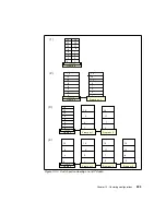
exist in the model frame and in the switched expansion frames. Figure 10-7
shows an example of a Single Stage SP Switch with both switched and
non-switched expansion frame configurations. There are four SP Switches and
each can support up to 16 processor nodes, a total of 64-nodes configuration.
Figure 10-7 Example on multiple SP-Switch-16 configurations
Frame configuration rule 8:
A maximum of three non-switched Tall expansion frames can be attached to
each Tall model frame or switched Tall expansion frame.
SPSwitch
Mix of
Additional
Thin/Wide or
High Node
SP Switch
Mix of
Additional
Thin/Wide or
High Node
SP Switch
Mix of
Additional
Thin/Wide or
High Node
SP Switch
Mix of
Additional
Thin/Wide or
High Node
N
o
n
s
w
it
c
h
e
d
E
x
p
a
n
s
io
n
F
ra
m
e
N
o
n
s
w
it
c
h
e
d
E
xp
a
n
s
io
n
F
ra
m
e
N
o
n
s
w
it
c
h
e
d
E
x
p
a
n
s
io
n
F
ra
m
e
N
o
n
s
w
it
c
h
e
d
E
x
p
a
n
s
io
n
F
ra
m
e
N
o
n
s
w
it
c
h
e
d
E
x
p
a
n
s
io
n
F
ra
m
e
N
o
n
s
w
it
c
h
e
d
E
xp
a
n
s
io
n
F
ra
m
e
N
o
n
s
w
it
c
h
e
d
E
xp
a
n
s
io
n
F
ra
m
e
N
o
n
s
w
it
c
h
e
d
E
x
p
a
n
s
io
n
F
ra
m
e
N
o
n
s
w
it
c
h
e
d
E
xp
a
n
s
io
n
F
ra
m
e
N
o
n
s
w
it
c
h
e
d
E
x
p
a
n
s
io
n
F
ra
m
e
N
o
n
s
w
it
c
h
e
d
E
x
p
a
n
s
io
n
F
ra
m
e
N
o
n
s
w
it
c
h
e
d
E
x
p
a
n
s
io
n
F
ra
m
e
For a more than five SP Switches configuration, an intermediate switch frame
is required, which can expand up to 128 nodes.
Содержание RS/6000 SP
Страница 2: ......
Страница 6: ...iv RS 6000 SP and Clustered IBM pSeries Systems Handbook...
Страница 16: ...xiv RS 6000 SP and Clustered IBM pSeries Systems Handbook...
Страница 48: ...24 RS 6000 SP and Clustered IBM pSeries Systems Handbook...
Страница 58: ...34 RS 6000 SP and Clustered IBM pSeries Systems Handbook Figure 2 4 375 MHz POWER3 High Node packaging...
Страница 60: ...36 RS 6000 SP and Clustered IBM pSeries Systems Handbook Figure 2 5 375 Mhz POWER3 SMP Wide Node packaging...
Страница 100: ...76 RS 6000 SP and Clustered IBM pSeries Systems Handbook...
Страница 182: ...158 RS 6000 SP and Clustered IBM pSeries Systems Handbook...
Страница 218: ...194 RS 6000 SP and Clustered IBM pSeries Systems Handbook...
Страница 284: ...260 RS 6000 SP and Clustered IBM pSeries Systems Handbook...
Страница 387: ...Appendix A Naming convention 363 IBM RS 6000 7017 Model S70 7017 S70 S70 Node name Machine type M T Nickname used here...
Страница 388: ...364 RS 6000 SP and Clustered IBM pSeries Systems Handbook...
Страница 436: ...412 RS 6000 SP and Clustered IBM pSeries Systems Handbook...
Страница 477: ...0 1 spine 0 1 0 169 53 89 pages RS 6000 SP and Clustered IBM pSeries Systems Handbook...
Страница 478: ......
Страница 479: ......


