background image

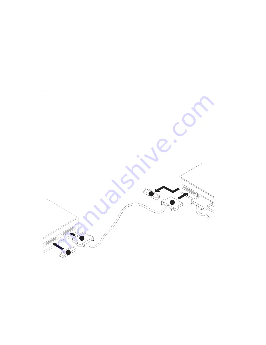
Step 9: Connect Any Additional External SCSI Devices

1. Locate the last SCSI device in the chain from the system unit. Remove the

SCSI device terminator.

2. Connect the new SCSI cable where you just removed the SCSI device

terminator.

3. Connect the other end of the SCSI cable to the new SCSI device.

4. Connect the SCSI device terminator.

5. Refer to the SCSI device documentation to set the SCSI device address. For

future reference, you can record the address in Appendix A of the User's Guide.

6. Repeat this step for each additional SCSI device you attach.

Last
SCSI
Device

SCSI  Device
Terminator

New
SCSI
Device

SCSI  Device
Terminator

3

1

2

4

New SCSI
Cable


  5

Содержание RS/6000 7043 43P Series

Страница 1: ...RS 6000 7043 43P Series IBM Setup Instructions SA38 0510 02...

Страница 2: ...nd or the program s described in this publication at any time without notice It is possible that this publication may contain reference to or information about products machines and programs programmi...

Страница 3: ...have internal options that are not installed go to Installing Optional Features in the User s Guide order number SA38 0511 03 shipped with your system Step 2 Check Your Inventory Books About Your Mach...

Страница 4: ...nd Caution notices Do not plug any cables into the system unit adapters or electrical outlets until you have reviewed this information Make sure none of the power cords are connected before continuing...

Страница 5: ...f you have a parallel device such as a printer connect it to the parallel connector If you have one serial device connect it to the serial connector S1 If you have an ASCII terminal you must connect i...

Страница 6: ...SCSI device terminator If this is the last device connected Note The built in SCSI interface is Fast Wide 16 bit SCSI 2 SE When a cable is not attached to the SCSI connector on the system unit the co...

Страница 7: ...tor 3 Connect the other end of the SCSI cable to the new SCSI device 4 Connect the SCSI device terminator 5 Refer to the SCSI device documentation to set the SCSI device address For future reference y...

Страница 8: ...ing the installation steps refer to the Customer Installable Options Library CD ROM for the documentation for the graphics adapter Change the settings for the display you are installing Step 11 Connec...

Страница 9: ...oroid Step 13 Connect the Adapter Cables If you are using any optional adapters such as Token Ring or 8 port EIA 232 connect the cables to the appropriate connectors in slots 1 2 3 4 or 5 Consult the...

Страница 10: ...hernet on page 9 For Thin 10 Base 2 for Model 140 and Model 240 100 10 Base 2 for Model 150 connect the Thin cable to the optional Transceiver 10 Base 2 for Model 140 and Model 240 100 10 Base 2 for M...

Страница 11: ...hernet cable to the ET connector 2 Lock the thick cable to the Ethernet connector by sliding the Ethernet connector toward the large notch Lock ET Connector 3 The thick Ethernet cable is now installed...

Страница 12: ...must use the vertical stand To attach the vertical stand place the system unit on the edge of a table To attach the vertical stand insert the tabs on the vertical stand into the slots in the side of...

Страница 13: ...tween 200v and 240v set the switch to 230 Attention The power supply voltage must be switched to match the voltage provided by your power outlets Turning on the system unit with the voltage selector s...

Страница 14: ...it display and attached devices 2 Plug these power cables into electrical outlets CAUTION This product is equipped with a three wire power cable and plug for your safety Use this power cable with a pr...

Страница 15: ...isplays up to 27 3 kg 60 lbs in weight 2 Be sure to maintain at least 50 mm 2 in of space at the rear of the system unit to allow for proper cooling To power on the system unlock the cover lock and sl...

Страница 16: ...IBM Part Number 08L0662 Printed in the United States of America on recycled paper containing 10 recovered post consumer fiber October 1998 SA38 51 2 8L 662...

Отзывы: