


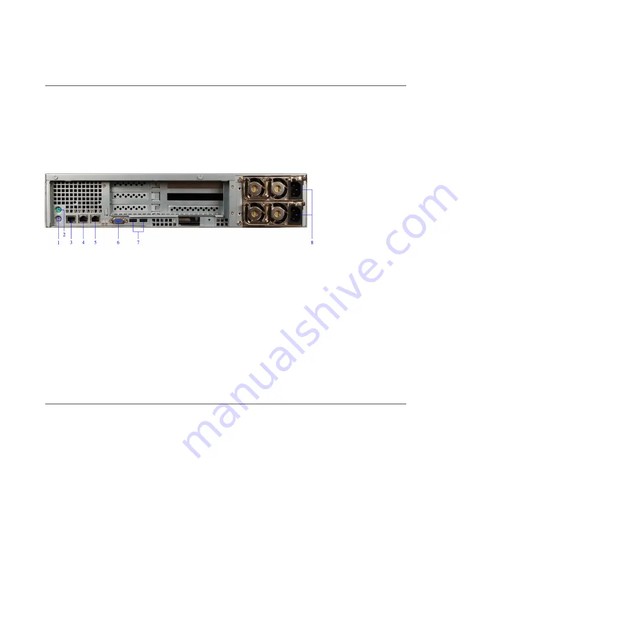
The SiteProtector SP2001 Appliance Back Panel
The SiteProtector SP2001 appliance back panel includes several different features
related to the power source, connections, and internal components.
SP2001 back panel
The following figure shows the SiteProtector SP2001 appliance back panel:
1.
Keyboard port
2.
Mouse port
3.
Serial port
4.
Management Interface (NIC)
5.
Unused port
6.
VGA port
7.
USB ports
8.
Power supplies
Note:
Use the VGA ports when you perform a procedure that requires a monitor
to be attached, such as restoring the SiteProtector SP2001 appliance to a supported
state on “Restoring Factory Defaults” on page 28.
Connecting the SiteProtector SP2001 Appliance
Procedure
1.
Connect the power cords to the SiteProtector SP2001 appliance and to the
power source.
Important:
You must connect both power cords to the SiteProtector SP2001
appliance to prevent warning signals from sounding.
2.
Connect the Ethernet cable from the network to the management port.
3.
Turn on the SiteProtector SP2001 appliance. “IBM ISS Proventia SP2001”
appears on the LCD panel.
Note:
It may take several minutes for this screen to appear.
Figure 2. SP2001 back panel
14
SiteProtector System: SP2001 Hardware Configuration
Содержание Proventia Management SiteProtector SP2001
Страница 5: ...iv SiteProtector System SP2001 Hardware Configuration ...
Страница 7: ...vi SiteProtector System SP2001 Hardware Configuration ...
Страница 21: ...Korean Class A Compliance Statement xx SiteProtector System SP2001 Hardware Configuration ...
Страница 27: ...6 SiteProtector System SP2001 Hardware Configuration ...
Страница 39: ...18 SiteProtector System SP2001 Hardware Configuration ...
Страница 47: ...26 SiteProtector System SP2001 Hardware Configuration ...
Страница 51: ...30 SiteProtector System SP2001 Hardware Configuration ...
Страница 55: ...34 SiteProtector System SP2001 Hardware Configuration ...
Страница 56: ......
Страница 57: ... Printed in USA ...


