


What to do next
Prepare the system for operation. For instructions, see “Preparing the 7063-CR1 system for operation after
you remove and replace internal parts” on page 68.
Removing and replacing PCIe adapters in the 7063-CR1
Learn how to remove and replace Peripheral Component Interconnect (PCI) Express (PCIe) adapters in
the IBM 7063-CR1 Hardware Management Console system.
Removing a PCIe adapter from the 7063-CR1 system
Learn how to remove a PCIe adapter from the IBM 7063-CR1 Hardware Management Console system.
Before you begin
Power off the system and place it in the service position. For instructions, see “Preparing the 7063-CR1
system to remove and replace internal parts” on page 66.
Procedure
1.
Attach the electrostatic discharge (ESD) wrist strap. The ESD wrist strap must be connected to an
unpainted metal surface until the service procedure is completed, and if applicable, until the service
access cover is replaced.
Attention:
v
Attach an electrostatic discharge (ESD) wrist strap to the front ESD jack, to the rear ESD jack, or to
an unpainted metal surface of your hardware to prevent the electrostatic discharge from damaging
your hardware.
v
When you use an ESD wrist strap, follow all electrical safety procedures. An ESD wrist strap is
used for static control. It does not increase or decrease your risk of receiving electric shock when
using or working on electrical equipment.
v
If you do not have an ESD wrist strap, just prior to removing the product from ESD packaging and
installing or replacing hardware, touch an unpainted metal surface of the system for a minimum of
5 seconds. If at any point in this service process you move away from the system, it is important to
again discharge yourself by touching an unpainted metal surface for at least 5 seconds before you
continue with the service process.
2.
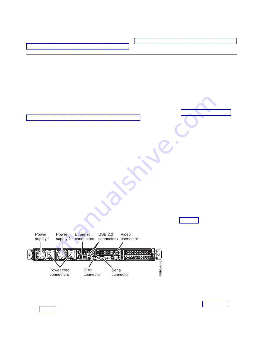
Label and remove any Ethernet cables that extend out of the adapter. See Figure 22.
3.
If you are working with the PCIe riser card in position 1 (UIO Network), complete the following
steps:
a.
Remove the two screws that secure the PCIe riser card to the chassis as shown in Figure 23 on
page 25.
b.
Lift the PCIe adapter riser at points (A) and (B) from the system backplane.
Figure 22. PCIe adapter positions
24
Power Systems: Servicing the 7063-CR1 Hardware Management Console system
Содержание Power Systems 7063-CR1
Страница 1: ...Power Systems Servicing the 7063 CR1 Hardware Management Console system IBM ...
Страница 2: ......
Страница 3: ...Power Systems Servicing the 7063 CR1 Hardware Management Console system IBM ...
Страница 16: ...xiv Power Systems Servicing the 7063 CR1 Hardware Management Console system ...
Страница 76: ...60 Power Systems Servicing the 7063 CR1 Hardware Management Console system ...
Страница 97: ...Figure 72 Connecting the power cords to the system Common procedures for servicing the 7063 CR1 81 ...
Страница 98: ...82 Power Systems Servicing the 7063 CR1 Hardware Management Console system ...
Страница 110: ...94 Power Systems Servicing the 7063 CR1 Hardware Management Console system ...
Страница 111: ......
Страница 112: ...IBM Printed in USA ...


