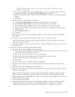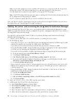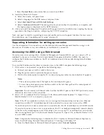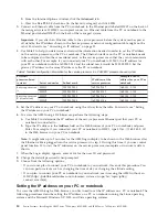
Before you begin, if you have not already done so, install and configure your SDMC. For instructions
about installing and configuring the SDMC, see Installing and configuring the SDMC(http://
publib.boulder.ibm.com/infocenter/director/v6r2x/topic/dpsm/dpsm_installing/
dpsm_installing_installing_dpsm_kickoff.html).
1.
If you want to directly attach your SDMC hardware appliance to the managed system, connect
Ethernet Connector 1
on the SDMC to the
LINK HMC1
port on the managed system.
To learn more about connecting an SDMC to a private network so that it can manage more than one
managed system, see Configuring the network (http://publib.boulder.ibm.com/infocenter/director/
v6r2x/topic/dpsm/dpsm_managing_console/configuringnetwork.html).
2.
Complete your server setup. For instructions, see “Completing server setup if you have an SDMC” on
page 33.
Cabling the server with an ASCII terminal
If you are not creating logical partitions, you can use an ASCII terminal to manage a server that is
running the AIX
®
, Linux, or VIOS operating systems. From the ASCII terminal, you can access the
Advanced System Management Interface (ASMI) to perform additional installation tasks.
The ASCII terminal is connected to the server through a serial link. The ASCII interface to the ASMI
provides a subset of the Web interface functions. The ASCII terminal is available only when the system is
in the standby state. It is not available during the initial program load (IPL) or run time.
Note:
If you are using a serial connection to the ASMI terminal, you must use a conversion cable. This
cable (part number 46K5108) is used to convert the ASCII terminal 9–pin Dshell connector to an RJ45
serial port connector on the system. For more information about the locations of the connectors on the
system, see 8202-E4B or 8205-E6B Locations (http://publib.boulder.ibm.com/infocenter/systems/scope/
hw/topic/p7ecs/p7ecsloccodes_72x_74x.htm).
To cable an ASCII terminal to the server, complete the following steps:
1.
By using a serial cable that is equipped with a null modem, connect the ASCII terminal to the system
connector 1 (P1-T1, which is the default) or 2 (P1-T2) on the rear of the server.
Cabling the server and setting up the console
23
Содержание Power 720 Express 8202-E4B
Страница 2: ......
Страница 6: ...iv Power Systems Installing the IBM Power 720 Express 8202 E4B and IBM Power 740 Express 8205 E6B...
Страница 22: ...10 Power Systems Installing the IBM Power 720 Express 8202 E4B and IBM Power 740 Express 8205 E6B...
Страница 50: ...38 Power Systems Installing the IBM Power 720 Express 8202 E4B and IBM Power 740 Express 8205 E6B...
Страница 63: ......
Страница 64: ...Part Number 16R3036 Printed in USA GI11 9821 02 1P P N 16R3036...


