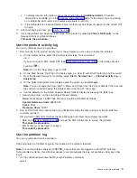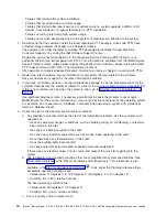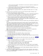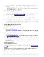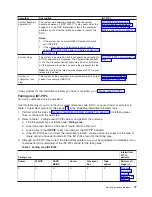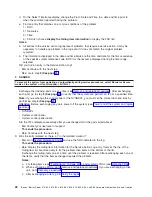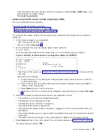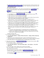
Once
the
problem
has
been
resolved,
close
the
log
entry
by
selecting
Close
a
NEW
entry
on
the
Service
Actions
Log
Report
display.
This
ends
the
procedure.
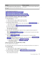
Cannot
perform
IPL
from
a
remote
location
(no
SRC)
For
use
by
authorized
service
providers.
This
topic
includes
the
following
sub-topics:
v
v
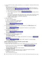
To
correct
the
IPL
problem,
perform
this
procedure
until
you
determine
the
problem
and
can
perform
a
remote
IPL.
1.
Is
the
system
powered
on
and
operating?
v
Yes
:
Continue
with
the
next
step.
v
No
:
Go
to
step
3
(See
page
.
2.
On
the
command
line,
enter
the
Display
System
Value
command:
DSPSYSVAL
QRMTIPL
Does
the
operating
system
have
the
correct
value
of
1
for
the
remote
power-on
function?
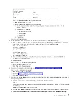
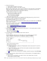
Figure
4.
Example
of
remote
power-on
configuration
display
for
QRMTIPL
+------------------------------------------------------------------------------+
|Display
System
Value
|
|System:
S0000000
|
|System
value
.
.
.
.
.
.
.
.
.
:
QRMTIPL
|
|Description
.
.
.
.
.
.
.
.
.
:
Remote
power
on
and
IPL
|
|Value
.
.
.
.
.
.
.
.
.
.
.
.
:
0
=
Not
allowed
|
|1
=
Allowed
|
+------------------------------------------------------------------------------+
v
Yes
:
Power
off
the
system
(see
Continue
with
the
next
step.
v
No
:
Perform
the
following:
a.
Change
the
value
to
1
by
entering
the
Change
System
Value
command
(
CHGSYSVAL
QRMTIPL
)
on
the
command
line.
b.
Power
off
the
system
by
entering
the
Power
Down
System
Immediate
command
(
PWRDWNSYS
*IMMED
)
on
the
command
line.
c.
Select
Normal
mode
on
the
control
panel.
d.
Verify
that
an
IPL
from
a
remote
location
completes
successfully
by
going
to
step
5
(See
page
.
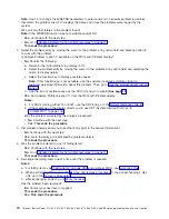
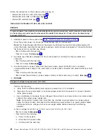
3.
Verify
that
all
external
communications
functions
are
operational,
such
as:
v
The
customer
is
using
the
correct
telephone
number.
v
The
telephone
line
is
operating
(dial
tone).
v
The
telephone
line
is
connected
or
plugged
in.
v
The
external
ECS
modem
is
powered
on.
v
The
external
ECS
modem
cable
is
connected
or
plugged
into
the
Comm
card
(CCIN
2745)
or
its
replacement.
v
The
modem
switches
are
set
or
jumper
wires
are
installed
for
the
type
of
communications
network
being
used.
v
The
cable
connecting
the
modem
to
the
communications
adapter
card
is
fastened
correctly.
4.
Select
Normal
mode
on
the
control
panel
if
it
is
not
already
selected
(see
in
the
iSeries
Service
Functions
).
Analyze
hardware
problems
23
Содержание iSeries Series
Страница 2: ......
Страница 504: ...492 iSeries iSeries Server 270 800 810 820 825 830 840 870 890 SB2 and SB3 Hardware Problem Analysis and Isolation...
Страница 508: ...496 iSeries iSeries Server 270 800 810 820 825 830 840 870 890 SB2 and SB3 Hardware Problem Analysis and Isolation...
Страница 511: ......
Страница 512: ...Printed in USA SY44 5914 01...

