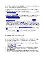
v
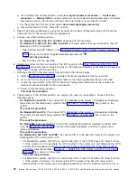
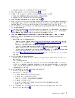
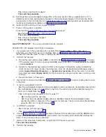
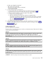
Yes
:
Move
the
cursor
to
another
IOA
assigned
to
the
IOP,
choosing
IOAs
with
a
status
of
″
unknown
″
or
″
disabled
″
before
moving
on
to
IOAs
with
a
status
of
″
operational.
″
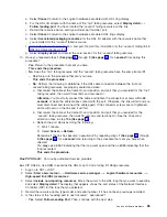
Go
to
step
14
(See
page
18.
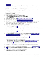
The
failing
IOA
is
located.
Exchange
the
I/O
adapter
that
you
just
powered
off.
Use
the
location
you
recorded
in
step
14
to
locate
the
IOA.
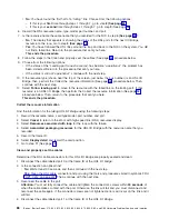
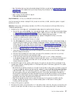
19.
Power
on
the
IOA
that
you
just
exchanged.
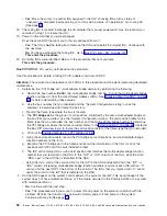
Does
the
same
SRC
that
sent
you
to
this
procedure
still
occur?
v
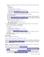
Yes
:
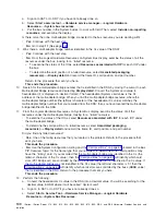
The
IOA
is
not
the
failing
item.
Remove
the
IOA
and
reinstall
the
original
IOA.
Continue
with
the
next
step.
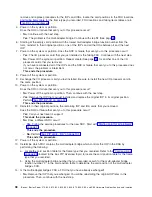
v
No
:
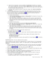
You
have
exchanged
the
failing
IOA.
Go
to
This
ends
the
procedure.
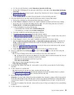
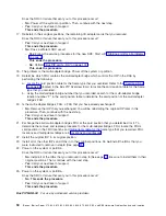
20.
No
failing
IOAs
were
identified.
Return
to
the
procedure
that
sent
you
here.
This
ends
the
procedure.
Bus
PIP
IOP-03:
For
use
by
authorized
service
providers.
Use
this
procedure
to
isolate
a
failing
PCI
I/O
adapter
card
from
an
SRC.
Attention:
The
removal
and
replacement
of
all
FRUs
in
this
procedure
must
be
performed
using
dedicated
maintenance.
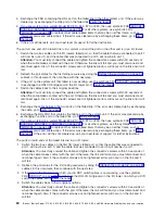
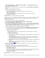
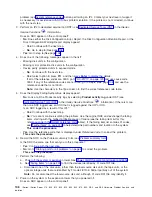
1.
Determine
the
″
PCI
bridge
set
″
(multi-adapter
bridge
domain)
by
performing
the
following:
a.
Record
the
bus
number
(BBBB),
the
multi-adapter
bridge
number
(C)
and
the
multi-adapter
bridge
function
number
(c)
from
the
Direct
Select
Address
(DSA).
See
for
help
in
determining
these
values.
b.
Use
the
bus
number
that
you
recorded
and
the
″
System
Configuration
Listing
″
or
ask
the
customer
to
determine
what
frame
the
bus
is
in.
c.
Record
the
frame
type
where
the
bus
is
located.
d.
The
PCI
bridge
set
is
the
group
of
card
positions
controlled
by
the
same
multi-adapter
bridge
on
the
bus
that
you
recorded.
Use
the
″
System
Configuration
Listing
″
,
the
card
position
table
for
the
frame
type
that
you
recorded,
the
bus
number,
and
the
multi-adapter
bridge
number
to
determine
the
PCI
bridge
set
where
the
failure
occurred.
Refer
to
the
(located
in
the
Bus
PIP
Overview
topic)
to
locate
the
card
position
table
for
the
frame
type
that
you
recorded.
e.
out
the
f.
Using
the
card
position
table,
record
the
PCI
bridge
set
card
positions,
and
multi-adapter
bridge
function
numbers
on
the
form.
g.
Examine
the
PCI
bridge
set
in
the
frame
and
record
the
information
on
the
form
for
all
of
the
positions
with
IOP
and
IOA
cards
installed
in
them.
h.
The
IOP
with
a
failing
IOA
is
in
the
card
position
that
matches
the
multi-adapter
bridge
function
number
that
you
recorded
in
the
DSA.
In
the
″
IOP
″
or
″
IOA
″
column
of
the
form,
write
the
word
″
DSA
″
next
to
the
IOP
that
is
identified
in
the
DSA.
i.
Using
the
form,
start
at
the
card
position
for
the
IOP
in
the
DSA
and
search
down
the
″
IOP
″
or
″
IOA
″
column
(increasing
multi-adapter
bridge
function
numbers)
and
mark
each
IOA
with
an
″
X
″
until
you
hit
the
next
IOP
or
the
bottom
of
the
column.
The
IOAs
that
you
marked
with
″
X
″
are
all
under
the
control
of
the
IOP
that
is
indicated
in
the
DSA.
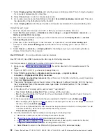
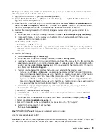
2.
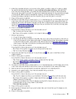
Did
the
SRC
appear
on
the
system
control
panel
or
the
system
console?
(This
would
happen
if
the
system
does
not
have
multiple
partitions,
or
if
the
failure
occurred
in
the
Primary
partition
of
a
system
with
multiple
partitions.)
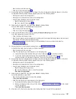
v
No
:
Continue
with
the
next
step.
v
Yes
:
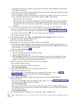
This
procedure
will
instruct
you
to
power
off
and
power
on
the
system
or
partition
with
the
problem.
Perform
that
function
as
you
would
normally
power
off
and
power
on
the
system.
Continue
with
step
4
(See
page
92
iSeries:
iSeries
Server
270,
800,
810,
820,
825,
830,
840,
870,
890,
SB2,
and
SB3
Hardware
Problem
Analysis
and
Isolation
Содержание iSeries Series
Страница 2: ......
Страница 504: ...492 iSeries iSeries Server 270 800 810 820 825 830 840 870 890 SB2 and SB3 Hardware Problem Analysis and Isolation...
Страница 508: ...496 iSeries iSeries Server 270 800 810 820 825 830 840 870 890 SB2 and SB3 Hardware Problem Analysis and Isolation...
Страница 511: ......
Страница 512: ...Printed in USA SY44 5914 01...

