background image

6.6.2 Nonoperating vibration

The disk drive withstands the following vibration levels without any loss or permanent damage.

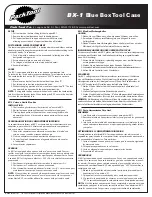
6.6.2.1 Random vibration

The test consists of a random vibration applied in each of three mutually perpendicular axes with the time
duration of 15 minutes per axis. The PSD levels for the test simulating the shipping and relocation envir-
onment are shown below.

0.018

500

0.018

40

0.03

5

0.001

2.5

G

2

/Hz

Hz

Figure 33. Random Vibration PSD Profile Breakpoints (nonoperating)

Note: Overall RMS (root mean square) level of vibration is 3.01 G rms.

6.6.2.2 Swept sine vibration

!

5 G (zero-to-peak), 10 to 500 to 10 Hz sine wave

!

0.5 oct/min sweep rate

!

25.4 mm (peak-to-peak) displacement, 5 to 10 to 5 Hz

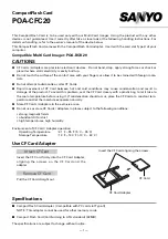
6.6.3 Operating shock

The hard disk drive meets the following criteria while operating in the conditions described below.

The shock test consists of ten shock inputs in each axis and direction for a total of 60.

There must be a minimum of 3 seconds delay between shock pulses.  Soft errors and automatic retries
are allowed during the test.  

The drive withstands the following half-sine shock pulse without any data loss or permanent damage.

15 G

180 G

All other models

15 G

150 G

48 GB model

Duration of 11 ms

Duration of 2 ms

Model

Figure 34. Operating shock

The input level shall be applied to the normal disk drive subsystem mounting points used to secure the
drive in a normal system.

Travelstar 48GH, 30GN & 15GN hard disk drive specifications

38

Содержание IC25N005ATDA04

Страница 1: ...IC25N005ATDA04 IC25N015ATDA04 IC25N006ATDA04 IC25N020ATDA04 IC25N007ATDA04 IC25N030ATDA04 IC25N010ATDA04 IC25T048ATDA05 Models IBM Hard disk drive specifications Travelstar 48GH 30GN 15GN 2 5 inch ATA IDE hard disk drive IBM storage products official published specifications ...

Страница 2: ...This page intentionally left blank ...

Страница 3: ...ication 1530 IC25N012ATDA04 IC25N005ATDA04 IC25N015ATDA04 IC25N006ATDA04 IC25N020ATDA04 IC25N007ATDA04 IC25N030ATDA04 IC25N010ATDA04 IC25T048ATDA05 Models IBM Hard disk drive specifications Travelstar 48GH 30GN 15GN 2 5 inch ATA IDE hard disk drive ...

Страница 4: ...s or typographical errors Changes are periodically made to the information herein these changes will be incorporated in new editions of the publication IBM may make improvements and or changes in the product s and or the program s described in this publication at any time It is possible that this publication may contain reference to or information about IBM products machines and programs programmi...

Страница 5: ...rror recovery 22 5 5 Data buffer test 22 5 4 WRITE safety 21 5 3 Equipment status 21 5 2 Write Cache 21 5 1 Data loss on power off 21 5 0 Data integrity 19 4 5 3 Operating modes 17 4 5 2 Mechanical positioning 16 4 5 1 Command overhead 16 4 5 Performance characteristics 13 4 4 Cylinder Allocation 12 4 3 Data sheet 11 4 2 Formatted capacity 11 4 1 Default logical drive parameters 11 4 0 Fixed disk ...

Страница 6: ...ace connector 45 7 1 Cabling 45 7 0 Electrical interface specifications 43 6 11 Packaging 43 6 10 5 Secondary circuit protection 43 6 10 4 Flammability 43 6 10 3 German Safety Mark 43 6 10 2 IEC compliance 43 6 10 1 UL and CSA approval 43 6 10 Safety 42 6 9 2 C Tick Mark 42 6 9 1 CE Mark 42 6 9 Electromagnetic compatibility 42 6 8 Identification labels 41 6 7 2 Discrete tone penalty 40 6 7 1 Sound...

Страница 7: ...lity for Power Modes 84 11 5 5 Status 84 11 5 4 Standby timer 84 11 5 3 Standby Sleep command completion timing 83 11 5 2 Power management commands 83 11 5 1 Power Mode 83 11 5 Power management features 82 11 4 1 Logical CHS addressing mode 82 11 4 Sector Addressing Mode 82 11 3 3 Required power off sequence 81 11 3 2 Emergency unload 81 11 3 1 Load Unload 81 11 3 Power off considerations 80 11 2 ...

Страница 8: ... vendor specific 121 13 6 Format Track 50h vendor specific 120 13 5 Flush Cache E7h 119 13 4 Execute Device Diagnostic 90h 118 13 3 Enable Disable Delayed Write FAh vendor specific 115 13 2 4 DEVICE CONFIGURATION SET subcommand C3h 115 13 2 3 DEVICE CONFIGURATION IDENTIFY subcommand C2h 115 13 2 2 DEVICE CONFIGURATION FREEZE LOCK subcommand C1h 114 13 2 1 DEVICE CONFIGURATION RESTORE subcommand C0...

Страница 9: ...Multiple C5h 191 13 38 Write Long 32h 33h 189 13 37 Write DMA CAh CBh 188 13 36 Write Buffer E8h 187 13 35 Standby Immediate E0h 94h 186 13 34 Standby E2h 96h 185 13 33 6 Error reporting 184 13 33 5 Self test log data structure 181 13 33 4 S M A R T error log sector 179 13 33 3 Device Attribute Thresholds data structure 174 13 33 2 Device Attributes Data Structure Travelstar 48GH 30GN 15GN hard di...

Страница 10: ...This page intentionally left blank ...

Страница 11: ...up of IC25N048ATDA04 0 28 Figure 24 Power consumption efficiency 27 Figure 23 DC Power requirements 26 Figure 22 Magnetic flux density limits 25 Figure 21 Limits of temperature and humidity 25 Figure 20 Environmental condition 23 Figure 19 Examples of error cases 19 Figure 18 Drive ready time for all models 19 Figure 17 Operating modes 18 Figure 16 Drive ready time 18 Figure 15 Latency time 18 Fig...

Страница 12: ...8h 111 Figure 74 Command Set Subcommand 110 Figure 73 Command set 2 of 2 109 Figure 73 Command set 1 of 2 99 Figure 72 Seek overlap 97 Figure 71 Device address map before and after Set Feature 96 Figure 70 Set Max security mode transition 95 Figure 69 Set Max SET PASSWORD data content 93 Figure 68 Command table for device lock operation 2 of 2 92 Figure 68 Command table for device lock operation 1...

Страница 13: ...esses 169 Figure 116 S M A R T Function Set command B0h 168 Figure 115 Sleep command E6h 99h 167 Figure 114 Set Multiple command C6h 165 Figure 113 Set Max ADDRESS F9h 163 Figure 112 Set Features command EFh 162 Figure 111 Sense Condition Command F0h 161 Figure 110 Seek command 7xh 160 Figure 109 Security Unlock information 159 Figure 108 Security Unlock command F2h 158 Figure 107 Security Set Pas...

Страница 14: ...This page intentionally left blank ...

Страница 15: ...1 000 000 000 bytes GB 1 000 000 000 bits Gb gravity a unit of force G field replacement unit FRU Federal Communications Commission FCC electrostatic discharge ESD Error Recovery Procedure ERP electromagnetic compatibility EMC European Economic Community EEC error correction code ECC Direct Memory Access DMA Drive Fitness Test DFT direct current DC cylinder Cyl Canadian Underwriters Laboratory C U...

Страница 16: ...llisecond ms millimeter mm Machine Level Control MLC megahertz MHz 1 000 00 bits per square inch Mb sq in 1 000 000 bytes per second MB sec 1 000 000 Bit per second Mb sec 1 000 000 Bit per second Mbps 1 000 000 bytes MB maximum max or Max meter m unit of A weighted sound power Lw logical block addressing LBA kilohertz KHz kilogram force centimeter kgf cm 1 000 Bit Per Inch Kbpi 1 000 000 bits per...

Страница 17: ...tle Handling Precaution 1 on page 4 Do not cover the breathing hole on the top cover See the figure title Handling Precaution 2 on page 4 Do not touch the interface connector pins or the surface of the printed circuit board The drive can be damaged by shock or ESD Electric Static Discharge Any damages incurred to the drive after removing it from the shipping package and the ESD protective bag are ...

Страница 18: ...1 4 Drive handling precautions Do not press on the drive cover during handling Figure 1 Handling Precaution 1 Figure 2 Handling Precaution 2 Travelstar 48GH 30GN 15GN hard disk drive specifications 4 ...

Страница 19: ...and 20 GB models 512 KB Upper 165 KB is used for firmware all other models Fast data transfer rate up to 100 MB sec Media data transfer rate 280 254 outer zone 155 141 inner zone Mb sec Average seek time 12 ms for read Closed loop actuator servo Embedded Sector Servo Rotary voice coil motor actuator Load Unload mechanism Mechanical latch Adaptive power save control 0 9 W at idle state 48 GB models...

Страница 20: ...position is Incompatible with DBOA DMCA DCRA DSOA and DPRA models Compatible with DTNA DLGA DDLA DTCA DPLA DYKA DYLA DADA DKLA DBCA DCXA DCYA DARA and DJSA models Travelstar 48GH 30GN 15GN hard disk drive specifications 6 ...

Страница 21: ...Part 1 Functional specification Travelstar 48GH 30GN 15GN hard disk drive specifications 7 ...

Страница 22: ...This page intentionally left blank ...

Страница 23: ...Servo No ID formatting Multizone recording Code 96 104 MTR ECC on the fly Enhanced Adaptive Battery Life Extender 3 2 Head disk assembly data The following technologies are used in each model Pico Slider Smooth glass disk GMR head Integrated lead suspension ILS Load unload mechanism Mechanical latch Travelstar 48GH 30GN 15GN hard disk drive specifications 9 ...

Страница 24: ...This page intentionally left blank ...

Страница 25: ...04 669 440 596A690h 63 16 16 383 48 IC25T048ATDA05 0 Customer Usable Data Bytes Word 60 61 LBA Word 6 Sect Trk Word 3 Head Word 1 Cyl Capacity GB Model Figure 3 Default logical drive parameters 4 2 Formatted capacity 15 103 033 344 20 003 880 960 30 005 821 440 48 004 669 440 Total Logical Data Bytes 29 498 112 39 070 080 58 605 120 93 759 120 Number of Sectors 16 383 16 383 16 383 16 383 Number o...

Страница 26: ...12 512 Bytes per Sector Physical Layout 5 GB model 6 GB model 7 5 GB model 10 GB model 12 GB model Description Figure 4 Formatted capacity by model number 2 of 2 4 3 Data sheet 16 16 16 16 Data bands 20 3 23 2 25 7 21 7 Areal density Gb sq in Max 47 5 47 5 51 47 5 Track density Ktpi 444 489 504 457 Recording density Kbpi Max 100 100 100 100 Interface transfer rate MB sec ULTRA DMA mode 5 105 199 1...

Страница 27: ...ors per Track Cylinder Zone Figure 6 Cylinder allocation 48 GB model IC25T048ATDA05 30 GB model 336 28160 30847 15 360 25600 28159 14 400 23552 25599 13 420 21248 23551 12 440 19968 21247 11 456 18688 19967 10 480 17408 18687 9 480 15616 17407 8 504 13568 15615 7 520 11264 13567 6 540 7936 11263 5 576 6400 7935 4 600 5120 6399 3 600 2816 5119 2 624 768 2815 1 640 0 767 0 Number of Sectors per Trac...

Страница 28: ... Figure 8 Cylinder allocation 20 GB model IC25N020ATDA04 15 GB 7 5 GB models 336 28160 30847 15 360 25600 28159 14 400 23552 25599 13 420 21248 23551 12 440 19968 21247 11 456 18688 19967 10 480 17408 18687 9 480 15616 17407 8 504 13568 15615 7 520 11264 13567 6 540 7936 11263 5 576 6400 7935 4 600 5120 6399 3 600 2816 5119 2 624 768 2815 1 640 0 767 0 Number of Sectors per Track Cylinder Zone Fig...

Страница 29: ... 15616 17663 8 420 13312 15615 7 440 11520 13311 6 456 9472 11519 5 480 7680 9471 4 480 5888 7679 3 504 4096 5887 2 520 2048 4095 1 540 0 2047 0 Number of Sectors per Track Cylinder Zone Figure 10 Cylinder allocation 12 GB 10 GB 6 GB 5 GB models IC25N012ATDA04 IC25N010ATDA04 IC25N006ATDA04 IC25N005ATDA04 Travelstar 48GH 30GN 15GN hard disk drive specifications 15 ...

Страница 30: ...e for each parameter Detailed descriptions are found in Section 5 0 100 100 100 100 100 Buffer host data transfer MB s 105 199 125 235 121 216 125 235 135 241 Disk buffer data transfer Mb s 1 0 1 0 1 0 1 0 1 0 Command overhead ms 3 0 3 0 3 0 3 0 5 0 Power on to ready sec 4200 4200 4200 4200 5400 Rotational Speed RPM 14 14 14 14 14 Average Random Seek Time For Write ms 12 12 12 12 12 Average Random...

Страница 31: ...ctuator to the start of a reliable read or write operation A reliable read or write operation implies that error correction recovery is not employed to cor rect arrival problems The Average Seek Time is measured as the weighted average of all possible seek combinations max Σ max 1 n Tnin Tnout n 1 Weighted Average ___________________________________________________ max 1 Tnin Tnout Where max maxim...

Страница 32: ...dels 5 5 11 1 5400 48 GB model Average Latency ms Time 1 revolution ms Rotational Speed RPM Model Figure 15 Latency time 4 5 2 5 Drive ready time 9 5 3 0 All other models Power On To Ready 9 5 5 0 48 GB model Power On To Ready Max sec Typical sec Model Condition Figure 16 Drive ready time This includes the time required for the internal self diagnostics Power On To Ready The condition in which the...

Страница 33: ...pable of accepting commands The spindle motor is stopped All circuitry but the host interface is in power saving mode The execution of commands is delayed until the spindle becomes ready Sleep The device requires a soft reset or a hard reset to be activated All electronics including spindle motor and host interface are shut off Figure 17 Operating modes 4 5 3 1 Mode transition time 9 5 1 8 Idle St...

Страница 34: ...This page intentionally left blank ...

Страница 35: ...oss confirm the completion of the actual write operation prior to the power off by issuing a Soft reset Hard reset Flush Cache command Standby command Standby Immediate command Sleep command Confirm the completion of the command 5 3 Equipment status The equipment status is available to the host system whenever the drive is not ready to read write or seek This status normally exists at the power on...

Страница 36: ...o reallocation to the host system The conditions for auto reallocation are described below 5 7 1 Nonrecovered write errors When a write operation cannot be completed after the Error Recovery Procedure ERP is fully carried out the sector or sectors are reallocated to the spare location An error is reported to the host system only when the write cache is disabled and the auto reallocation has failed...

Страница 37: ... the byte is bad On The Fly correctable Byte 0 1 2 3 4 5 6 7 8 9 0 1 2 3 4 5 6 7 1 1 1 1 1 1 1 1 Interleave A B C A B C A B C A B C A B C A B C A B C Error pattern 5 Error byte for each interleave X X X X X X X X X X X X X X X O O O Error pattern 5 5 5 5 5 X X X X X X X X X O O O X X X X X X Uncorrectable Byte 0 1 2 3 4 5 6 7 8 9 0 1 2 3 4 5 6 7 1 1 1 1 1 1 1 1 Interleave A B C A B C A B C A B C A...

Страница 38: ...This page intentionally left blank ...

Страница 39: ...radient Altitude Operating conditions Figure 20 Environmental condition Note The system is responsible for providing sufficient air movement to maintain surface temperatures below 60 C at the center of the top cover and below 63 C at the center of the drive circuit board assembly Maximum storage period with shipping package is one year Specification Environment 0 10 20 30 40 50 60 70 80 90 100 45 ...

Страница 40: ... The drive functions without experiencing degradation of the soft error rate under the following magnetic flux density limits at the surface of the enclosure 0 5 201 400 1 101 200 2 5 61 100 5 0 60 Limits Gauss RMS Frequency KHz Figure 22 Magnetic flux density limits 6 1 2 2 Conductive noise The disk drive functions without degradation of the soft error rate in the frequency range from DC to 20 MH...

Страница 41: ...rage 0 65 0 65 0 9 Low Power Idle average 0 85 0 95 1 3 Active Idle average 3 1 85 1 85 2 0 Performance Idle average Notes All other models Watts typical 30 GB 20 GB models Watts typical 48 GB model Watts typical Description Notes 1 The maximum fixed disk ripple is measured at the 5 volt input of the HDD 2 The disk drive shall not incur damage for an over voltage condition of 25 maximum duration o...

Страница 42: ...Consumption Efficiency Watts GB 5 GB 6 GB 7 5 GB 10 GB 12 GB 15 GB 20 GB 30 GB 48 GB Capacity Figure 24 Power consumption efficiency Note Power consumption efficiency is calculated as Power Consumption of Low Power Idle Watt Capacity GB Travelstar 48GH 30GN 15GN hard disk drive specifications 28 ...

Страница 43: ...6 3 Start up Current 0 5 sec div 0 2 A div Figure 25 Typical current wave form at start up of IC25N048ATDA04 0 Travelstar 48GH 30GN 15GN hard disk drive specifications 29 ...

Страница 44: ...iv Figure 26 Typical current wave form at start up of IC25N030ATDA04 0 0 5 sec div 0 2 A div Figure 27 Typical current wave form at start up of IC25N015ATDA04 0 Travelstar 48GH 30GN 15GN hard disk drive specifications 30 ...

Страница 45: ...ition The drive is designed to be used under the following conditions The drive should be operated within specifications of shock vibration temperature humidity altitude and magnetic field The drive should be protected from ESD The breathing hole in the top cover of the drive should not be covered Force should not be applied to the cover of the drive The specified power requirements of the drive s...

Страница 46: ...coil The actuator velocity is greater than the normal case and the unload process is inherently less controllable without a normal seek current profile Emergency unload is intended to be invoked in rare situations Because this operation is inherently uncontrolled it is more mechanically stressful than a normal unload The drive supports a minimum of 20 000 emergency unloads 6 4 6 2 Required Power O...

Страница 47: ... Section 5 2 Write Cache on page 21 6 4 6 4 Test considerations Start stop testing is classically performed to verify head disk durability In the case of IC25XXXXATDAxx x the heads do not land on the disk so this type of test should be viewed as a test of the load unload function Start Stop testing should be done by commands through the interface not by power cycling the drive Simple power cycling...

Страница 48: ... 0 25 69 85 0 25 9 5 0 2 30 GB and 20 GB models 155 Max 100 2 0 25 69 85 0 25 12 5 0 2 48 GB model Weight gram Length mm Width mm Height mm Model Figure 28 Physical dimensions and weight 6 5 2 Mounting hole locations The mounting hole locations and size of the hard disk drive are shown below Figure 29 Mounting hole locations for all models except 48 GB model Travelstar 48GH 30GN 15GN hard disk dri...

Страница 49: ...ve will operate in all axes 6 directions and will stay within the specified error rates when tilted 5 degrees from these positions Performance and error rate will stay within specification limits if the drive is operated in the other permissible orientations from which it was formatted Thus a drive formatted in a horizontal orientation will be able to run vertically and vice versa The recommended ...

Страница 50: ...ration or spindle rotation 6 5 5 Load unload mechanism The head load unload mechanism is provided to protect the disk data during shipping movement or storage Upon power down a head unload mechanism secures the heads at the unload position See Section 6 6 4 Nonoperating shock on page 39 for additional details Travelstar 48GH 30GN 15GN hard disk drive specifications 36 ...

Страница 51: ...he test will be 30 minutes of random vibration using the power spectral density PSD levels specified in C S 1 9711 002 1990 03 as V5L The vibration test level for V5L is 0 67 G RMS Root Mean Square 5 0 x 104 500 5 0 x 104 200 1 0 x 103 150 1 0 x 103 65 8 0 x 103 62 8 0 x 103 48 1 1 x 10³ 45 1 1 x 10³ 17 2 0 x 105 5 G2 Hz Hz Figure 31 Random vibration PSD profile breakpoints operating 6 6 1 2 Swept...

Страница 52: ... sine wave 0 5 oct min sweep rate 25 4 mm peak to peak displacement 5 to 10 to 5 Hz 6 6 3 Operating shock The hard disk drive meets the following criteria while operating in the conditions described below The shock test consists of ten shock inputs in each axis and direction for a total of 60 There must be a minimum of 3 seconds delay between shock pulses Soft errors and automatic retries are allo...

Страница 53: ... All other models 120 G 700 G 48 GB model Duration of 11 ms Duration of 1 ms Model Figure 35 Nonoperating shock The shocks are applied in each direction of the three mutually perpendicular axes of the drive one axis at a time Input levels are measured at the frame of the drive Travelstar 48GH 30GN 15GN hard disk drive specifications 39 ...

Страница 54: ... tests are to be conducted with the drive supported by spacers so that the lower surface of the drive is located 25 3 mm above the chamber floor No sound absorbing material shall be used The acoustical characteristics of the disk drive are measured under the following conditions Mode definitions Ÿ Idle mode Power on disks spinning track following unit ready to receive and respond to control line c...

Страница 55: ... following formula only when determining compliance Lwt spec Lw 0 1Pt 0 3 4 0 Bels where Lw A weighted sound power level Pt Value of desecrate tone penalty dLt 6 0 dBA dLt Tone to noise ratio taken in accordance with ISO 7779 at each octave band Travelstar 48GH 30GN 15GN hard disk drive specifications 41 ...

Страница 56: ...d exercised with a random accessing routine at maximum data rate the drive meets the following worldwide electromagnetic compatibility EMC requirements United States Federal Communications Commission FCC Rules and Regulations Class B Part 15 RFI Suppression German National Requirements RFI Japan VCCI Requirements of IBM products EU EMC Directive Technical Requirements and Conformity Assessment Pro...

Страница 57: ... used in this product are made of material with a UL recognized flammability rating of V 1 or better The flammability rating is marked or etched on the board All other parts not con sidered electrical components are made of material with a UL recognized flammability rating of V 1 or better except minor mechanical parts 6 10 5 Secondary circuit protection This product utilizes printed circuit wirin...

Страница 58: ...This page intentionally left blank ...

Страница 59: ...tors and Cable Assembly of the ATA ATAPI 5 document The figure below and Figure 29 on page 34 show the connector location and physical pin location 43 44 22 Pin Pin 19 1 2 A C B D Figure 37 Interface connector pin assignments Note 1 Pin position 20 is left blank for correct connector insertion Note 2 Pin positions A B C and D are used for drive address setting Refer to Figure 51 on page 62 for cor...

Страница 60: ...8 04 3 state I O DD07 03 GND 02 TTL I RESET 01 Type I O SIGNAL PIN Type I O SIGNAL PIN Figure 38 Table of signals Notes O designates an output from the Drive I designates an input to the Drive I O designates an input output common OD designates an Open Drain output The signal lines marked with are redefined during the Ultra DMA protocol to provide special functions These lines change from the conv...

Страница 61: ...Y Read Operation DIOW STOP DIOR HSTROBE IORDY DDMARDY Write Operation Conventional Definition Special Definition for Ultra DMA Figure 39 Special signal definitions for Ultra DMA Travelstar 48GH 30GN 15GN hard disk drive specifications 47 ...

Страница 62: ...er Otherwise this signal is in high impedance state regardless of the state of the IRQ bit The interrupt is set when the IRQ bit is set by the drive CPU The IRQ is reset to zero by a host read of the status register or a write to the Command Register This signal is a 3 state line with 24 mA of sink capability IOCS16 A signal indicating to the host that a 16 bit wide data register has been addresse...

Страница 63: ...tion of the cable connector in order to avoid incorrect insertion is recommended IORDY This signal indicated to the host that the drive is ready to complete the current I O cycle This line is driven low at the falling edge of DIOR or DIOW when HDD needs one or more additional WAIT cycles to extend the PIO cycle This line can be connected to the host IORDY signal in order to insert one or more WAIT...

Страница 64: ...a transfer in an Ultra DMA mode signals the termination of the burst DDMARDY Ultra DMA This signal is used only for Ultra DMA data transfers between host and drive The signal DDMARDY is a flow control signal for Ultra DMA data out bursts This signal is held asserted by the device to indicate to the host that the device is ready to receive Ultra DMA data out transfers The device may negate DDMARDY ...

Страница 65: ...rent 2 4 V min 0 5 V max Output High Voltage Output Low Voltage Outputs 2 0 V min 5 5 V max 0 5 V min 0 8 V max Input High Voltage Input Low Voltage Inputs 7 6 Reset timings t10 t1 RESET BUSY 25 RESET low width t10 9 5 RESET high to Not BUSY t1 Max µ µs Min µ µs PARAMETER DESCRIPTION Figure 40 System reset timings Travelstar 48GH 30GN 15GN hard disk drive specifications 51 ...

Страница 66: ...d to IORDY active tRD 10 DIOR DIOW to address valid hold t9 30 Address valid to IOCS16 released t8 40 Address valid to IOCS16 assertion t7 30 DIOR data tristate t6z 5 DIOR data hold t6 20 DIOR data setup t5 10 DIOW data hold t4 20 DIOW data setup t3 25 DIOR DIOW recovery time t2i 70 DIOR DIOW pulse width t2 25 Address valid to DIOR DIOW setup t1 120 Cycle time t0 MAX ns MIN ns PARAMETER DESCRIPTIO...

Страница 67: ...Q delay DIOW to DMARQ delay tLR tLW 25 DIOR negated pulse width DIOW negated pulse width tKR tKW 5 DIOR DIOW to DMACK hold tJ 0 DMACK to DIOR DIOW setup tI 10 DIOW data hold tH 20 DIOR DIOW data setup tG 5 DIOR data hold tF 50 DIOR data access tE 70 DIOR DIOW asserted pulse width tD 120 Cycle time t0 MAX ns MIN ns PARAMETER DESCRIPTION Figure 42 Multiword DMA cycle timings Travelstar 48GH 30GN 15G...

Страница 68: ...0 10 10 10 10 Maximum time allowed for output drivers to release tAZ 38 57 86 115 154 230 Two cycle time t2CYC 16 8 25 39 54 73 112 Cycle time tCYC 90 120 0 130 0 170 0 200 0 230 0 First DSTROBE time tFS 0 0 0 0 0 0 Minimum time before driving IORDY tZIORDY 50 20 55 20 55 20 70 20 70 20 70 20 Envelope time tENV 20 20 20 20 20 20 Setup time for DMACK tACK 0 0 0 0 0 0 Unlimited interlock time tUI MA...

Страница 69: ...MAX ns MIN ns MAX ns MIN ns MAX ns MIN ns MAX ns MIN ns MAX ns MIN ns MODE 5 MODE 4 MODE 3 MODE 2 MODE 1 MODE 0 PARAMETER DESCRIPTION Note When a host does not satisfy the tSR timing the host should be ready to receive two more data words after HDMARDY is negated Figure 44 Ultra DMA cycle timings Host Pausing Read Travelstar 48GH 30GN 15GN hard disk drive specifications 55 ...

Страница 70: ...S 20 20 20 20 20 20 Interlock time with minimum tMLI 20 20 20 20 20 20 Minimum delay time required for output tZAH 10 10 10 10 10 10 Maximum time allowed for output drivers to release tAZ 75 0 100 0 100 0 150 0 150 0 150 0 Limited interlock time tLI 85 100 100 100 125 160 Ready to pause time tRP 50 60 60 60 70 75 HDMARDY to final DSTROBE time tRFS MAX ns MIN ns MAX ns MIN ns MAX ns MIN ns MAX ns M...

Страница 71: ...evice tCS 20 20 20 20 20 20 Interlock time with minimum tMLI 20 20 20 20 20 20 Maximum delay time required for output tZAH 10 10 10 10 10 10 Maximum time allowed for output drivers to release tAZ 75 0 100 0 100 0 150 0 150 0 150 0 Limited interlock time tLI 50 50 50 50 50 50 Time from DSTROBE edge to negation of DMARQ tSS MAX ns MIN ns MAX ns MIN ns MAX ns MIN ns MAX ns MIN ns MAX ns MIN ns MAX ns...

Страница 72: ... 39 54 73 112 Cycle time tCYC 75 0 100 0 100 0 150 0 150 0 150 0 Limited interlock time tLI 0 0 0 0 0 0 Minimum time before driving IORDY tZIORDY 55 20 55 20 55 20 70 20 70 20 70 20 Envelope time tENV 20 20 20 20 20 20 Setup time for DMACK tACK 0 0 0 0 0 0 Unlimited interlock time tUI MAX ns MIN ns MAX ns MIN ns MAX ns MIN ns MAX ns MIN ns MAX ns MIN ns MAX ns MIN ns MODE 5 MODE 4 MODE 3 MODE 2 MO...

Страница 73: ...s MAX ns MIN ns MAX ns MIN ns MAX ns MIN ns MAX ns MIN ns MAX ns MIN ns MODE 5 MODE 4 MODE 3 MODE 2 MODE 1 MODE 0 PARAMETER DESCRIPTION Note When a device does not satisfy the tSR timing the device is ready to receive two more data words after DDMARDY is negated Figure 48 Ultra DMA cycle timings Device Pausing Write Travelstar 48GH 30GN 15GN hard disk drive specifications 59 ...

Страница 74: ...ice tCH 4 5 7 7 10 15 CRC word setup time at device tCS 20 20 20 20 20 20 Interlocking time with minimum tMLI 75 0 100 0 100 0 150 0 150 0 150 0 Limited interlock time tLI 85 100 100 100 125 160 Ready to pause time tRP 50 60 60 60 70 75 DDMARDY to final HSTROBE time tRFS MAX ns MIN ns MAX ns MIN ns MAX ns MIN ns MAX ns MIN ns MAX ns MIN ns MAX ns MIN ns MODE 5 MODE 4 MODE 3 MODE 2 MODE 1 MODE 0 PA...

Страница 75: ... hold time at device tCH 4 5 7 7 10 15 CRC word setup time at device tCS 20 20 20 20 20 20 Interlock time with minimum tMLI 75 0 100 0 100 0 150 0 150 0 150 0 Limited interlock time tLI 50 50 50 50 50 50 Time from HSTROBE edge to assertion of STOP tSS MAX ns MIN ns MAX ns MIN ns MAX ns MIN ns MAX ns MIN ns MAX ns MIN ns MAX ns MIN ns MODE 5 MODE 4 MODE 3 MODE 2 MODE 1 MODE 0 PARAMETER DESCRIPTION ...

Страница 76: ... pin 28 is ground or low the drive is a Master If pin 28 is open or logic high the drive is a Slave 1 2 3 4 5 3 1 4 2 1 Device 0 Master 2 Device 1 Slave 3 Cable Select 4 Never attach a jumper here 5 Never attach a jumper here Note When pin C is grounded the drive does not spin up at POR Figure 51 Drive address setting 7 11 Drive default address setting The default setting of jumper at shipment is ...

Страница 77: ...to address Control Block registers The following table shows the I O address map Device control Reg Alt Status Reg 0 1 1 0 1 Control Block Registers Command Reg Status Reg 1 1 1 1 0 Drive Head Reg Drive Head Reg 0 1 1 1 0 Cylinder high Reg Cylinder high Reg 1 0 1 1 0 Cylinder low Reg Cylinder low Reg 0 0 1 1 0 Sector number Reg Sector number Reg 1 1 0 1 0 Sector count Reg Sector count Reg 0 1 0 1 ...

Страница 78: ...This page intentionally left blank ...

Страница 79: ...Part 2 Interface specification Travelstar 48GH 30GN 15GN hard disk drive specifications 65 ...

Страница 80: ...This page intentionally left blank ...

Страница 81: ...ng new functions included by ATA ATAPI 5 standards or newer standards The Travelstar 48GH 30GN 15GN supports the following functions as Vendor Specific Functions Address Offset Feature Format Unit Function ENABLE DISABLE DELAYED WRITE SENSE CONDITION command 8 2 Terminology Interrupt request Device or Host INTRQ The first command that is executed after the power on reset also known as a hard reset...

Страница 82: ...This page intentionally left blank ...

Страница 83: ...s the prefailure attributes exceed their corresponding thresholds For example a Power On Hours Attribute never results in a negative reliability status S M A R T Return Status WRITE VERIFY command does not include read verification after write operation The function is the same as WRITE SECTORS command Write Verify Standby timer is enabled by STANDBY command or IDLE command The value in the Sector...

Страница 84: ...This page intentionally left blank ...

Страница 85: ...imped x 0 1 A N Not used Data bus high imped x x 0 A N Control block registers Not used Data bus high imped 1 x x x N N WRITE DIOW READ DIOR DA0 DA1 DA2 CS1 CS0 Functions Addresses x can be either 2 Mapping of registers in LBA mode N signal not asserted 1 imped impedance A signal asserted Logic conventions Figure 53 Register Set Communication to or from the device is through an I O Register that r...

Страница 86: ... up before writing to the Command Register 10 3 Cylinder High Register This register contains the high order bits of the starting cylinder address for any disk access At the end of the command this register is updated to reflect the current cylinder number In LBA Mode this register contains Bits 16 23 At the end of the command this register is updated to reflect the current LBA Bits 16 23 The cyli...

Страница 87: ...1 is in the Status Register 10 6 Device Control Register 0 0 1 IEN 2 SRST 3 1 4 5 6 7 Device Control Register Figure 55 Device Control Register Bit Definitions Interrupt Enable When IEN 0 and the device is selected the device interrupts to the host will be enabled When IEN 1 or the device is not selected the device interrupts to the host will be disabled IEN Software Reset The device is held at re...

Страница 88: ...ts are updated to reflect the currently selected head The head number may be from zero to the number of heads minus one In LBA mode HS3 through HS0 contain bits 24 27 of the LBA At command completion these bits are updated to reflect the current LBA bits 24 27 HS3 HS2 HS1 HS0 Device When DRV 0 device 0 master is selected When DRV 1 device 1 Slave is selected DRV Binary encoded address mode select ...

Страница 89: ...T ABT ID Not Found When IDN 1 it indicates that the requested sector s ID field could not be found IDNF IDN Uncorrectable Data Error When UNC 1 it indicates that an uncorrectable data error has been encountered UNC Interface CRC Error When CRC 1 it indicates that a CRC error has occurred on the data bus during a Ultra DMA transfer ICRCE CRC 10 9 Features Register This register is command specific ...

Страница 90: ...s Register continuously Therefore the host should not attempt to use IDX bit for timing purposes IDX Corrected Data Corrected Data is always 0 CORR COR Data Request Bit DRQ 1 indicates that the device is ready to transfer a word or byte of data between the host and the device The host should not write the Command register when DRQ 1 DRQ Device Seek Complete If DSC 1 it indicates that a Seek has co...

Страница 91: ... Soft Reset Software Reset The RESET signal is negated in the ATA Bus The device resets the interface circuitry and sets the default values Hard Reset Hardware Reset The device executes a series of electrical circuitry diagnostics spins up the HDA tests speed and other mechanical parametric and sets default values Power On Reset POR The actions of each reset are shown in Figure 59 on page 78 Trave...

Страница 92: ...ng Device operation o o Aborting Host interface soft reset hard reset POR o execute x not execute Note 1 Execute after the data in write cache has been written 2 The default value on POR is shown in Figure 60 on the next page 3 The Set Features command with Feature register CCh enables the device to revert these parameters to the power on defaults 4 In the case of sleep mode the device goes to sta...

Страница 93: ...ure 60 Default Register Values As a result of carrying out an Execute Device Diagnostic command or being powered on or if a hard reset occurs the system generates an Error Register diagnostic code See the table below for a description of the various codes Device 1 failed 8xh Controller microprocessor error 05h ECC circuitry error 04h Sector buffer error 03h Formatter device error 02h No error dete...

Страница 94: ...it DASP is asserted by Device 0 and Device 1 if it is present in order to indicate device active Soft Reset DASP is read by Device 0 to determine if Device 1 is present If Device 1 is present Device 0 shall read PDIAG to determine when it is valid to clear the BSY bit and whether Device 1 has powered on or reset without error otherwise Device 0 clears the BSY bit whenever it is ready to accept com...

Страница 95: ...hen HDD power is interrupted while the heads are still loaded the microcode cannot operate and the normal 5V power is unavailable to unload the heads In this case normal unload is not possible so the heads are unloaded by routing the back EMF of the spinning motor to the voice coil The actuator velocity is greater than the normal case and the unload process is inherently less controllable without ...

Страница 96: ...media The drive supports both Logical CHS Addressing Mode and LBA Addressing Mode as the sector addres sing mode The host system may select either the currently selected CHS translation addressing or LBA addressing on a command by command basis by using the L bit in the DEVICE HEAD register A host system must set the L bit to 1 if the host uses LBA Addressing mode 11 4 1 Logical CHS addressing mod...

Страница 97: ...eature set provides a set of commands and a timer that enables a device to implement low power consumption modes The drive implements the following set of functions 1 A Standby timer 2 Idle command 3 Idle Immediate command 4 Sleep command 5 Standby command 6 Standby Immediate command 11 5 1 Power Mode The device is in execution of a command or accessing the disk media with the read look ahead func...

Страница 98: ...device to automatically enter standby mode from either active or idle mode following a host programmed period of inactivity If the device is in the active or idle mode the device waits for the specified time period and if no command is received the device automa tically enters the standby mode If the value of the SECTOR COUNT register on Idle command or the Standby command is set to 00h the device...

Страница 99: ... power management levels contain discrete bands described in the section of Set Feature command in detail This feature set uses the following functions Ÿ A SET FEATURES subcommand to enable Advanced Power Management Ÿ A SET FEATURES subcommand to disable Advanced Power Management The Advanced Power Management feature is independent of the Standby timer setting If both Advanced Power Management lev...

Страница 100: ...y sophisticated data analysis algorithms to predict the likelihood of near term degradation or fault condition By alerting the host system of a negative reliability status condition the host system can warn the user of the impending risk of a data loss and advise the user of appropriate action Since S M A R T utilizes the internal device microprocessor and other device resources there may be some ...

Страница 101: ...ribute thresholds then the device reliability status is negative indicating an impending degrading or faulty condition 11 7 5 S M A R T commands The S M A R T commands provide access to attribute values attribute thresholds and other logging and reporting information 11 7 6 S M A R T operation with power management modes It is recommended that when a host system utilizes both the power management ...

Страница 102: ...The User Password should be given or changed by a system user When the User Password is set the device enables the Device Lock Function and then the device is locked on the next power on reset or hard reset User Password When the Master Password is set the device does NOT enable the Device Lock Function and the device CANNOT be locked with the Master Password but the Master Password can be used fo...

Страница 103: ...the next time the device is powered on Setting password POR Set Password with User Password Normal operation Power off Device locked mode POR Ref No setting password POR Normal operation Power off Device unlocked mode POR Figure 65 Initial setting Travelstar 48GH 30GN 15GN hard disk drive specifications 89 ...

Страница 104: ...ject Complete Complete Erase Unit Lock function Disable Normal operation All commands are available Freeze Lock command Enter Device Frozen mode Normal Operation expect Set Password Disable Password Erase Unit Unlock commands Enter Device Unlock mode N Y N Y Erase Prepare Media Access Non media Access Match 1 refers to the commands in Figure 68 Command table for device lock operation on pages 92 a...

Страница 105: ... CMD with Master Password Normal operation Figure 67 Password lost 11 8 5 5 Attempt limit for the SECURITY UNLOCK command The SECURITY UNLOCK command has an attempt limit which helps to prevent a user from attempting to unlock the drive with various passwords numerous times The device counts the password mismatch If the password does not match the device counts it without distinguishing the Master...

Страница 106: ...Read Sector s w o retry o o o Read Native Max ADDRESS o o x Read Multiple o o x Read Long w retry o o x Read Long w o retry o o x Read DMA w retry o o x Read DMA w o retry o o o Read Buffer o o o Initialize Device Parameters o o o Idle Immediate o o o Idle o o o Identify Device DMA o o o Identify Device o o x Format Unit o o x Format Track o o o Flush Cache o o o Execute Device Diagnostic o o o En...

Страница 107: ...ute Thresholds o o o S M A R T Read Attribute Values o o o S M A R T Execute Off line Immediate o o o S M A R T Enable Operations o o o S M A R T Enable Disable Attribute Autosave o o o S M A R T Disable Operations o o o Sleep o o o Set Multiple Mode o o o Set Max UNLOCK Device Frozen Mode Device Unlocked Mode Device Locked Mode Command o Device executes command normally x Device terminates comman...

Страница 108: ...1 032 192 0FC000h Customer usable sector count 528 482 304 byte 528MB Customer usable device size 16 384 004000h Required blocks for protected area 8 388 608 byte Required size for protected area 1 048 575 0FFFFFh Max LBA native 536 870 912 byte 536MB Capacity native 1 Shipping HDDs from the HDD manufacturer When the HDD is shipped from the manufacturer the device has been tested to have a capacit...

Страница 109: ...ode Feature set When the password is set the device is in the Set Max Unlocked mode This command requests a transfer of a single sector of data from the host The following figure defines the content of this sector of information The password is retained by the device until the next power cycle When the device accepts this command the device is in Set Max Unlocked mode Reserved 17 255 Password 32 b...

Страница 110: ... persist over a power cycle but persist over a hardware or software reset NOTE If this command is immediately preceded by a Read Native MAX ADDRESS command regardless of Feature register value it shall be interpreted as a Set Max ADDRESS command Set Max Inactive Set Max SET PASSWORD Set Max UNLOCK Set Max Unlocked Set Max LOCK Set Max Locked Set Max FREEZE LOCK Set Max Frozen Figure 70 Set Max sec...

Страница 111: ... on Reset If Reverting to Power on Defaults has been enabled by Set Features command it is cleared by Soft reset as well Upon entering offset mode the capacity of the drive returned in the Identify Device data is the size of the former protected area A subsequent Set Max Address command with the address returned by the Read Max Address command allows access to the entire drive Addresses wrap so th...

Страница 112: ...is in Address Offset mode 11 10 3 Exceptions in Address Offset Mode Any commands which access sectors across the original native maximum LBA are rejected with error even if the access protection is removed by a Set Max Address command Read Look Ahead operation is not carried out even if it is enabled by the Set Feature command Travelstar 48GH 30GN 15GN hard disk drive specifications 98 ...

Страница 113: ...wever actual seek operation for the next seek command starts right after completion of the actual seek operation for the first seek command The execution of two seek commands overlaps excluding the actual seek operation With this overlap total elapsed time for a number of seek commands is the total accumulated time for the actual seek operation plus one pre and post overhead When the number of see...

Страница 114: ...y command except the Write command is issued the operation to write the data from the cache buffer into the media is begun Power consumption can be reduced by Delayed Write When Write commands come with a long interval the device must exit from the power saving mode and enter into the power saving mode again without Delayed Write function If Delayed Write is enabled such power saving mode transiti...

Страница 115: ...eted after the Error Recovery Procedure ERP is fully carried out the sector s are reallocated to the spare location An error is reported to the host system only when the write cache is disabled and the auto reallocation fails If the number of available spare sectors reaches 16 sectors the write cache function will be disabled automatically If the command is without retry and the write cache functi...

Страница 116: ...This page intentionally left blank ...

Страница 117: ...terrupts are cleared when the host reads the Status Register issues a reset or writes to the Command Register Figure 136 on page 197 shows time out values of the device 12 1 Data In commands These commands are Device Configuration IDENTIFY Identify Device Read Buffer Read Long Read Multiple Read Sectors S M A R T Read Attribute Values S M A R T Read Attribute Thresholds S M A R T Read log sector E...

Страница 118: ...ector is transferred to the host If the device detects an invalid parameter then it will abort the command by setting BSY 0 ERR 1 ABT 1 and interrupting the host If an error occurs the device will set BSY 0 ERR 1 and DRQ 1 The device will then store the error status in the Error Register and interrupt the host The registers will contain the location of the sector in error The error location will b...

Страница 119: ... The device sets BSY 0 and DRQ 1 when it is ready to receive a sector or block b The host writes one sector or block of data via the Data Register c The device sets BSY 1 after it has received the sector or block d When the device has finished processing the sector or block it sets BSY 0 and interrupts the host e In response to the interrupt the host reads the Status Register f The device clears t...

Страница 120: ...host If an uncorrectable error occurs the device will set BSY 0 and ERR 1 store the error status in the Error Register and interrupt the host The registers will contain the location of the sector in error The error location will be reported with CHS mode or LBA mode The mode is decided by the mode select bit bit 6 of the Device Head register on issuing the command All data transfers to the host th...

Страница 121: ...o sav S M A R T Enable Disable Automatic Off line S M A R T Enable Operations S M A R T Execute Off line Immediate S M A R T Return Status S M A R T Save Attribute Values Standby Standby Immediate Execution of these commands involves no data transfer 1 The host writes any required parameters to the Features Sector Count Sector Number Cylinder and Device Head Registers 2 The host writes the command...

Страница 122: ...ets the DMA channel prior to reading status from the device The DMA protocol allows high performance multitasking operating systems to eliminate processor overhead associated with PIO transfers 1 The host initializes the Slave DMA channel 2 The host writes any required parameters to the Features Sector Count Sector Number Cylinder and Device Head registers 3 The host writes command code to the Com...

Страница 123: ...0 E4 Read Buffer 1 0 0 0 0 0 0 0 0 00 NOP 3 1 1 0 0 1 0 0 1 C9 Read DMA no retry 4 1 1 0 0 1 0 0 0 C8 Read DMA retry 4 1 1 1 0 0 1 0 0 E4 Read Buffer 1 1 0 0 1 0 0 0 1 91 Initialize Device Parameters 3 1 0 0 1 0 1 0 1 95 Idle Immediate 3 1 1 1 0 0 0 0 1 E1 Idle Immediate 3 1 0 0 1 0 1 1 1 97 Idle 3 1 1 1 0 0 0 1 1 E3 Idle 3 1 1 1 0 1 1 1 0 EE Identify Device DMA 4 1 1 1 0 1 1 0 0 EC Identify Devic...

Страница 124: ...ad Attribute Thresholds 1 1 0 1 1 0 0 0 0 B0 S M A R T Read Attribute Values 1 1 0 1 1 0 0 0 0 B0 S M A R T Execute Off line Immediate 3 1 0 1 1 0 0 0 0 B0 S M A R T Enable Operations 3 1 0 1 1 0 0 0 0 B0 S M A R T Enable Disable Automatic Off line 3 1 0 1 1 0 0 0 0 B0 S M A R T Enable Disable Attribute Auto save 3 1 0 1 1 0 0 0 0 B0 S M A R T Disable Operations 3 1 0 0 1 1 0 0 1 99 Sleep 3 1 1 1 ...

Страница 125: ... feature 03 EF Set Transfer mode 02 EF Enable Write Cache Set Features DB B0 S M A R T Enable Disable Automatic Off line DA B0 S M A R T Return Status D9 B0 S M A R T Disable Operations D8 B0 S M A R T Enable Operations D6 B0 S M A R T Write Log Sector D5 B0 S M A R T Read Log Sector D4 B0 S M A R T Execute Off line Immediate D3 B0 S M A R T Save Attribute Values D2 B0 S M A R T Enable Disable Att...

Страница 126: ...his bit is used by Set Max ADDRESS command V Valid This indicates that the bit is part of an output parameter and should be specified x This indicates that the hex character is not used This indicates that the bit is not used Input Registers 0 This indicates that the bit is always set to 0 1 This indicates that the bit is always set to 1 H Head number This indicates that the head number part of th...

Страница 127: ...IDX COR DRQ DSC DF RDY BSY AMN T0N ABT 0 IDN 0 UNC CRC 0 1 2 3 4 5 6 7 0 1 2 3 4 5 6 7 Status Register Error Register Figure 75 Check Power Mode command E5h 98h The Check Power Mode command will report whether the device is spun up and the media is available for immediate access Input Parameters From The Device Sector Count This indicates the power mode code The command returns FFh in the Sector C...

Страница 128: ...evice Configuration Overlay feature set commands are identified by the value placed in the Features register The table below shows these Features register values Reserved other DEVICE CONFIGURATION SET C3h DEVICE CONFIGURATION IDENTIFY C2h DEVICE CONFIGURATION FREEZE LOCK C1h DEVICE CONFIGURATION RESTORE C0h Command Value Figure 77 Device Configuration Overlay Features register values 13 2 1 DEVIC...

Страница 129: ...f optional commands modes or feature sets supported by a device as indicated by a DEVICE CONFIGURATION IDENTIFY command The DEVICE CONFIGURATION SET command transfers an overlay that modifies some of the bits set in words 63 82 83 84 and 88 of the IDENTIFY DEVICE command response When the bits in these words are cleared the device no longer supports the indicated command mode or feature set If a b...

Страница 130: ...e 2 and below are supported 2 1 Ultra DMA mode 3 and below are supported 3 1 Ultra DMA mode 4 and below are supported 4 1 Ultra DMA mode 5 and below are supported 5 Reserved 15 6 Ultra DMA modes supported 2 1 Multiword DMA mode 0 is supported 0 1 Multiword DMA mode 1 and below are supported 1 1 Multiword DMA mode 2 and below are supported 2 Reserved 15 3 Multiword DMA modes supported 1 Data Struct...

Страница 131: ...mpt to disable any feature enabled 04h Device s feature is already modified with DCO 03h Device is now Security Locked mode 02h DCO feature is frozen 01h error reason code description Sector count invalid bit location Cylinder low invalid word location Cylinder high Figure 79 DCO error information definition Travelstar 48GH 30GN 15GN hard disk drive specifications 117 ...

Страница 132: ...ster Error Register Figure 80 Enable Disable Delayed Write command FAh The Enable Disable Delayed Write command sets if the Delayed Write function is enabled or disabled Delayed Write function is enabled or disabled according to the feature register s value Even if the Delayed Write function is enabled by this command Delayed Write does not work when the Write Cache function is disabled For detail...

Страница 133: ...V V V V V V V 0 ERR IDX COR DRQ DSC DF RDY BSY AMN T0N ABT 0 IDN 0 UNC CRC 0 1 2 3 4 5 6 7 0 1 2 3 4 5 6 7 Status Register Error Register Figure 81 Execute Device Diagnostic command 90h The Execute Device Diagnostic command performs the internal diagnostic tests implemented by the device The results of the test are stored in the Error Register The normal Error Register bit definitions do not apply...

Страница 134: ...ut Registers V 0 V 0 V 0 0 0 V 0 0 0 0 0 ERR IDX COR DRQ DSC DF RDY BSY AMN T0N ABT 0 IDN 0 UNC CRC 0 1 2 3 4 5 6 7 0 1 2 3 4 5 6 7 Status Register Error Register Figure 82 Flush Cache command E7h This command causes the device to complete writing data from its cache The device returns a status of RDY 1 and DSC 1 50h after following sequence Data in the write cache buffer is written to the disk me...

Страница 135: ...be initialized to zero with the write operation At this time the read operation is not verified for the correct sector of data initialization Any data previously stored on the track will be lost Output Parameters To The Device Sector Number In LBA mode this register specifies that LBA address bits 0 7 are to be formatted L 1 Cylinder High Low This indicates the cylinder number of the track to be f...

Страница 136: ...s the Error Register An Abort error ABT 1 will be returned under the following conditions Ÿ The descriptor value does not match the certain value except 00h In LBA mode this command formats a single logical track including the specified LBA Travelstar 48GH 30GN 15GN hard disk drive specifications 122 ...

Страница 137: ...ilable right after this command s completion This commands completion is also used on the next power on reset or hard reset Both previous information data are erased from the device by this command Note that the Format Unit command initializes from LBA 0 to Native MAX LBA Host MAX LBA is set by Initialize Drive Parameter or Set MAX ADDRESS command is ignored The protected area by Set MAX ADDRESS c...

Страница 138: ...shown below 8 min 5 GB model 8 min 6 GB model 10 min 7 5 GB model 14 min 10 GB model 16 min 12 GB model 20 min 15 GB model 24 min 20 GB model 38 min 30 GB model 52 min 48 GB model Travelstar 48GH 30GN 15GN hard disk drive specifications 124 ...

Страница 139: ...Input Registers Command Block Output Registers V 0 0 V 0 0 0 V 0 0 0 0 0 ERR IDX COR DRQ DSC DF RDY BSY AMN T0N ABT 0 IDN 0 UNC CRC 0 1 2 3 4 5 6 7 0 1 2 3 4 5 6 7 Status Register Error Register Figure 85 Identify Device command ECh The Identify Device command requests the device to transfer configuration information to the host The device will transfer a sector to the host containing the informat...

Страница 140: ...ired to spin up and IDENTIFY DEVICE response is complete C837H 02 Number of cylinders in default translate mode Note 1 01 Reserved 0 0 1 hard sectored 1 1 1 identify data incomplete 2 0 1 not MFM encoded 3 1 1 head switch time 15 us 4 1 1 spindle motor control option implemented 5 0 1 fixed drive 6 1 1 removable cartridge drive 7 0 1 disk transfer rate 5 Mbps 8 0 1 disk transfer rate 5 Mbps but 10...

Страница 141: ...ord 15 3 0 Reserved 2 1 1 Word 88 is Valid 1 1 1 Word 64 70 are Valid 0 1 1 Word 54 58 are Valid XXX7H 53 DMA data transfer cycle timing mode Refer Word 62 and 63 0200H 52 PIO data transfer cycle timing mode 0200H 51 Capabilities 15 0 0 the contents of word 50 are valid 14 1 1 the contents of word 50 are valid 13 1 0 Reserved 0 0 1 the device has a minimum Standby timer value that is device specif...

Страница 142: ...ersion number ATA ATAPI 5 T13 1321D Revision 1 0015H 81 Major version number ATA 1 ATA 2 ATA 3 and ATA ATAPI 4 ATA ATAPI 5 003CH 80 Reserved 0000H 69 79 Minimum PIO Transfer Cycle Time With IORDY Flow Control 15 0 78 Cycle time in nanoseconds 120ns 16 6MB s 0078H 68 Minimum PIO Transfer Cycle Time Without Flow Control 15 0 F0 Cycle time in nanoseconds 240ns 8 3MB s 00F0H 67 Manufacturer s Recommen...

Страница 143: ... 1 SMART self test supported 0 x 1 SMART error logging supported 400xH 84 Command set supported 15 0 Always 14 1 Always 13 12 0 Reserved 11 1 1 Device Configuration Overlay command supported 10 9 0 Reserved 8 1 1 SET MAX security extension supported 7 1 1 Address Offset feature supported 6 0 1 SET FEATURES subcommand required to spin up 5 1 1 Power Up In Standby feature set supported 4 0 1 Removab...

Страница 144: ...ed 0 1 1 UltraDMA mode 0 is supported XX3FH 88 Command set feature enabled 15 0 Always 14 1 Always 13 2 0 Reserved 1 x 1 SMART self test supported 0 x 1 SMART error logging supported 4000H 87 Command set feature enabled 15 12 0 Reserved 11 x 1 Device Configuration Overlay supported 10 9 0 1 Reserved 8 1 1 Device Configuration Overlay supported 7 X 1 Address Offset mode enabled 6 0 1 SET FEATURES s...

Страница 145: ...1 Device 1 passed diagnostic 10 9 X how Device 1 determined the device number 00 Reserved 01 a jumper was used 10 the CSEL signal was used 11 some other method was used or the method is unknown 8 1 Always 7 0 Device 0 hardware reset result Device 1 clears these bits to 0 7 0 Reserved 6 X 1 Semi dupliex mode is enabled 5 X 1 Device 0 detected Device 1 4 X 1 Device 1 passed diagnostic 3 X 1 Device 0...

Страница 146: ... XXXXH 130 Current Set Feature Option Bit assignments 15 4 0 Reserved 3 X 1 Auto reassign enabled 2 X 1 Reverting enabled 1 X 1 Read Look ahead enabled 0 X 1 Write Cache enabled 000XH 129 Description Content Word Figure 86 Identify device information 7 of 7 Note The mark in the Content field indicates the use of those parameters that are vendor specific Travelstar 48GH 30GN 15GN hard disk drive sp...

Страница 147: ...heads 3FFFh Number of cylinders IC25N012ATDA04 0 1C21B00h Number of user addressable sectors 02B6h 347KB Buffer size 10h Number of heads 3FFFh Number of cylinders IC25N015ATDA04 0 2542980h Number of user addressable sectors 0E1Ch 1 806k Buffer size 10h Number of heads 3FFFh Number of cylinders IC25N020ATDA04 0 37E3E40h Number of user addressable sectors 0E1Ch 1 806KB Buffer size 10h Number of head...

Страница 148: ...sters Command Block Output Registers V 0 0 V 0 0 0 V 0 0 0 0 0 ERR IDX COR DRQ DSC DF RDY BSY AMN T0N ABT 0 IDN 0 UNC CRC 0 1 2 3 4 5 6 7 0 1 2 3 4 5 6 7 Status Register Error Register Figure 88 Identify Device DMA command EEh The Identify Device DMA command requests the device to transfer configuration information to the host The device will transfer the same 256 words of device identification da...

Страница 149: ...he point timer begins counting down IF the device s power save mode is already an idle mode the device remains in that mode When the Idle mode is entered the device is spun up to operating speed If the device is already spinning the spin up sequence is not executed During Idle mode the device is spinning and is ready to respond to host commands immediately Output Parameters To The Device Sector Co...

Страница 150: ...R IDX COR DRQ DSC DF RDY BSY AMN T0N ABT 0 IDN 0 UNC CRC 0 1 2 3 4 5 6 7 0 1 2 3 4 5 6 7 Status Register Error Register Figure 90 Idle Immediate command E1h 95h The Idle Immediate command causes the device to enter Performance Idle mode The device is spun up to operating speed If the device is already spinning the spin up sequence is not executed During Idle mode the device is spinning and ready t...

Страница 151: ...rs command 91h The Initialize Device Parameters command enables the host to set the number of sectors per track and the number of heads minus 1 per cylinder Words 54 58 in Identify Device Information reflects these parameters The parameters remain in effect until the following events occur Another Initialize Device Parameters command is received The device is powered off A hard reset occurs A soft...

Страница 152: ... RDY BSY AMN T0N ABT 0 IDN 0 UNC CRC 0 1 2 3 4 5 6 7 0 1 2 3 4 5 6 7 Status Register Error Register Figure 92 Read Buffer command E4h The Read Buffer command transfers a sector of data from the sector buffer of the device to the host The sector is transferred through the Data Register 16 bits at a time The sector transferred will be from the same part of the buffer written to by the last Write Buf...

Страница 153: ...sferred through the Data Register 16 bits at a time The host initializes a slave DMA channel prior to issuing the command The data transfers are qualified by the DMARQ and are performed by the slave DMA channel The device issues only one interrupt per command to indicate that the data transfer has terminated and that status is available If an uncorrectable error occurs the read will be terminated ...

Страница 154: ...less an unrecoverable error occurs Sector Number This indicates the sector number of the last transferred sector L 0 In LBA mode this register contains the current LBA bits 0 7 L 1 Cylinder High Low This indicates the cylinder number of the last transferred sector L 0 In LBA mode this register contains the current LBA bits 8 15 Low and bits 16 23 High L 1 H This indicates the head number of the se...

Страница 155: ...the device will keep setting DRQ 1 to indicate that the device is ready to transfer the ECC bytes to the host The data is transferred 16 bits at a time and the ECC bytes are transferred 8 bits at a time The number of ECC bytes are 4 or 40 according to the setting of Set Feature option The default setting is 4 bytes of ECC data The command makes a single attempt to read the data and does not check ...

Страница 156: ... number of the transferred sector L 0 In LBA mode this register contains current LBA bits 8 15 Low 16 23 High L 1 H This indicates the head number of the transferred sector L 0 In LBA mode this register contains current LBA bits 24 27 L 1 The device internally uses 40 bytes of ECC data on all data written or read from the disk The 4 byte mode of operation is provided via an emulation Use of the 40...

Страница 157: ...sfers the data from the device to the host The sectors are transferred through the Data Register 16 bits at a time The command execution is identical to the Read Sectors command with one exception an interrupt is generated for each block as defined by the Set Multiple command instead of for each sector Output Parameters To The Device Sector Count This indicates the number of continuous sectors to ...

Страница 158: ...or L 0 In LBA mode this register contains the current LBA bits 0 7 L 1 Cylinder High Low This indicates the cylinder number of the last transferred sector L 0 In LBA mode this register contains the current LBA bits 8 15 Low and bits 16 23 High L 1 H This indicates the head number of the last transferred sector L 0 In LBA mode this register contains the current LBA bits 24 27 L 1 Travelstar 48GH 30...

Страница 159: ...Max ADDRESS command Even if the Address Offset mode is enabled the native max LBA CYL of HDD is returned Output Parameters To The Device L LBA mode This indicates the addressing mode An L 0 specifies CHS mode and L 1 specifies the LBA addressing mode D This is the device number bit Indicates that the device number bit of the Device Head Register should be specified D 0 selects the master device an...

Страница 160: ...n the CHS mode this register contains the native maximum head number L 0 V Valid Indicates that the bit is part of an input parameter and will be set to 0 or 1 by the device This indicates that the bit is not used Travelstar 48GH 30GN 15GN hard disk drive specifications 146 ...

Страница 161: ...ata from disk media and then transfers the data from the device to the host The sectors are transferred through the Data Register 16 bits at a time If an uncorrectable error occurs the read will be terminated at the failing sector Output Parameters To The Device Sector Count The number of continuous sectors to be transferred If zero is specified then 256 sectors will be transferred Sector Number T...

Страница 162: ...r L 0 In LBA mode this register contains the current LBA bits 0 7 L 1 Cylinder High Low This is the cylinder number of the last transferred sector L 0 In LBA mode this register contains the current LBA bits 8 15 Low and bits 16 23 High L 1 H This is the head number of the last transferred sector L 0 In LBA mode this register contains the current LBA bits 24 27 L 1 Travelstar 48GH 30GN 15GN hard di...

Страница 163: ...ectors command verifies one or more sectors on the device No data is transferred to the host The difference between the Read Sectors command and Read Verify Sectors command is data is transferred to the host during a Read Sectors command data is not transferred to the host during a Read Verify Sectors command If an uncorrectable error occurs the read verify will be terminated at the failing sector...

Страница 164: ... an unrecoverable error occurs Sector Number This is the sector number of the last transferred sector L 0 In LBA mode this register contains the current LBA bits 0 7 L 1 Cylinder High Low This is the cylinder number of the last transferred sector L 0 In LBA mode this register contains the current LBA bits 8 15 Low and bits 16 23 High L 1 H This is the head number of the last transferred sector L 0...

Страница 165: ...d Block Input Registers Command Block Output Registers V 0 V 0 V 0 0 V V 0 0 0 0 0 ERR IDX COR DRQ DSC DF RDY BSY AMN T0N ABT 0 IDN 0 UNC CRC 0 1 2 3 4 5 6 7 0 1 2 3 4 5 6 7 Status Register Error Register Figure 99 Recalibrate command 1xh The Recalibrate command moves the read write heads from anywhere on the disk to cylinder 0 If the device cannot reach cylinder 0 T0N Track 0 Not Found will be se...

Страница 166: ...ng information specified in Figure 101 Then the device checks the transferred password If the User Password or Master Password matches the given password the device disables the security mode feature device lock function This command does not change the Master Password which may be reactivated later by setting User Password This command should be executed in device unlock mode Reserved 17 255 Pass...

Страница 167: ... 0 0 0 0 ERR IDX COR DRQ DSC DF RDY BSY AMN T0N ABT 0 IDN 0 UNC CRC 0 1 2 3 4 5 6 7 0 1 2 3 4 5 6 7 Status Register Error Register Figure 102 Security Erase Prepare command F3h The Security Erase Prepare command must be issued immediately before the Security Erase Unit command to enable device erasing and unlocking The Security Erase Prepare Command must be issued immediately before the Format Uni...

Страница 168: ...Unit command initializes all user data sectors and then disables the device lock function Note that the Security Erase Unit command initializes from LBA 0 to Native MAX LBA The Host MAX LBA is set by the Initialize Drive Parameter or the Set MAX ADDRESS command is ignored The protected area by the Set MAX ADDRESS command is also initialized This command requests the transfer of a single sector of ...

Страница 169: ...diately prior to the Security Erase Unit command If the device receives a Security Erase Unit command without a prior Security Erase Prepare command the device aborts the security erase unit command This command disables the security mode feature device lock function however the master password is still stored internally within the device and may be reactivated later when a new user password is se...

Страница 170: ...0N ABT 0 IDN 0 UNC CRC 0 1 2 3 4 5 6 7 0 1 2 3 4 5 6 7 Status Register Error Register Figure 105 Security Freeze Lock command F5h The Security Freeze Lock Command allows the device to enter frozen mode immediately After this command is completed the command which updates Security Mode Feature Device Lock Function is rejected Frozen mode is quit only by a Power off The following commands are reject...

Страница 171: ...F1h The Security Set Password command enables the security mode feature device lock function and sets the master password or the user password The security mode feature device lock function is enabled by this command and the device is not locked immediately The device is locked after the next power on reset or hard reset When the MASTER password is set by this command the master password is regist...

Страница 172: ...Code is not set The Revision Code field is returned in the Identify Device word 92 The valid Revision Codes are 0000h to FFFDh The Default Master Password Revision Code is FFFEh The code FFFFh is reserved The setting of the Identifier and Security level bits interact as follows Identifier User Security level High The password supplied with the command will be saved as the new user pass word The se...

Страница 173: ...ed the device will be in device lock mode The password has not been changed yet The Security Unlock command requests to transfer a single sector of data from the host including information specified in Figure 109 below If the Identifier bit is set to master and the file is in high security mode then the password supplied will be compared with the stored master password If the file is in maximum se...

Страница 174: ... the device regards Password as the Master Password The user can detect if the attempt to unlock the device has failed due to a mismatched password as this is the only reason that an abort error will be returned by the file AFTER the password information has been sent to the device If an abort error is returned by the device BEFORE the password data has been sent to the file then another problem e...

Страница 175: ...designated track and selects the designated head The device does not need to be formatted for a seek to execute properly Output Parameters To The Device Sector Number In LBA mode this register specifies the LBA address bits 0 7 for seek L 1 Cylinder High Low This is the cylinder number of the seek In LBA mode this register specifies the LBA address bits 8 15 Low and bits 16 23 High for seek L 1 H ...

Страница 176: ...o sense temperature in a device This command is executable without spinning up even if a device is started with No Spin Up option If this command is issued at the temperature out of range which is specified for operating condition the error might be returned with IDN bit 1 Not recommendable condition for start up If over stressed condition is detected this bit will be set to one N Temperature is h...

Страница 177: ...N ABT 0 IDN 0 UNC CRC 0 1 2 3 4 5 6 7 0 1 2 3 4 5 6 7 Status Register Error Register Figure 112 Set Features command EFh The Set Feature command establishes the following parameters which affect the execution of certain features as shown in the table below ABT will be set to 1 in the Error Register if the Feature register contains any undefined values After the power on reset or hard reset the dev...

Страница 178: ...nn 00001 PIO Flow Control Transfer Mode x 001 00000 PIO Default Transfer Mode Disable IORDY 000 00000 PIO Default Transfer Mode When the Feature register is 05h Enable Advanced Power Management the Sector Count Register specifies the Advanced Power Management level Aborted 00h FFh The deepest Power Saving mode is Standby 01h 7Fh The deepest Power Saving mode is Low power Idle 80h BFh The deepest P...

Страница 179: ...L which is set via this command as a default value This command implement SET MAX security extension commands as subcommands But regardless of Feature register value the case this command is immediately preceded by a Read Native Max ADDRESS command it is interpreted as a Set Max ADDRESS command The Read Native Max ADDRESS command should be issued and completed immediately prior to issuing the Set ...

Страница 180: ...be set L 1 In CHS mode this register contains the cylinder number which is to be input L 0 H In LBA mode this register contains LBA bits 24 27 which are to be input L 1 In CHS mode this register is ignored L 0 L This indicates the LBA addressing mode L 0 specifies the CHS mode and L 1 specifies the LBA addressing mode D This indicates the device number bit The device number bit of the Device Head ...

Страница 181: ...the device to perform Read and Write Multiple commands and establishes the block size for these commands The block size is the number of sectors to be transferred for each interrupt The default block size after power up or hard reset is 0 The Read Multiple and Write Multiple commands are disabled If an invalid block size is specified an Abort error will be returned to the host The Read Multiple an...

Страница 182: ...4 5 6 7 Status Register Error Register Figure 115 Sleep command E6h 99h This command is the only way to cause the device to enter Sleep Mode When this command is issued the device confirms the completion of the cached write commands before it asserts INTRQ Then the device is spun down and the interface becomes inactive The only way to recover from Sleep Mode is with a software reset or a hardware ...

Страница 183: ...es the Attribute Thresholds and other low level subcommands that can be used for logging and reporting purposes and to accommodate special user needs The S M A R T Function Set command has several separate subcommands which are selectable via the device s Features Register when the S M A R T Function Set command is issued by the host In order to select a subcommand the host must write the subcomma...

Страница 184: ...uses the auto save feature to be disabled The state of the Attribute Autosave feature either enabled or disabled will be preserved by the device across the power cycle A value of 00h written by the host into the device s Sector Count Register before issuing the S M A R T Enable Disable Attribute Autosave subcommand will cause this feature to be disabled Disabling this feature does not preclude the...

Страница 185: ...utine and service the host within two seconds after receipt of the new command After servicing the interrupting command the device will resume its routine automatically or not start its routine depending on the interrupting command Captive mode When executing self test in captive mode the device sets BSY to one and executes the specified self test routine after receipt of the command At the end of...

Страница 186: ...ations subcommand from the host the device asserts BSY disables S M A R T capabilities and functions clears BSY and asserts INTRQ After receipt of the device of the S M A R T Disable Operations subcommand from the host all other S M A R T subcommands with the exception of S M A R T Enable Operations are disabled and invalid and will be aborted by the device including the S M A R T Disable Operatio...

Страница 187: ... memory during some other normal operation such as during a power on during a power off sequence or during an error recovery sequence A value of one written by the host into the device s Sector Count register before issuing this subcommand shall cause the off line read scanning feature to be disabled The Device does not perform the off line read scanning at the off line data collection activities ...

Страница 188: ... R T capability 1Bh 1 16Fh 1 Off line data collection capability 2 1 16Eh 1 Current segment pointer 2 1 16Ch 2 Total time in seconds to complete off line data collection activity 2 1 16Bh 1 Self test execution status 2 1 16Ah 1 Off line data collection status 2 1 15Eh 12 30th Device Attribute 2 1 02h 12 1st Device Attribute 0010h binary 00h 2 Data Structure Revision Number Value Format Offset Byte...

Страница 189: ...erved may either 0 Bit 1 On line Collection Bit 0 Pre Failure Advisory bit flags 01h 2 Status Flags binary 00h 1 Attribute ID Number 01h to FFh Value Offset Byte Description Figure 119 Individual Attribute Data Structure Attribute ID Numbers Any non zero value in the Attribute ID Number indicates an active attribute The device supports following Attribute ID Numbers The names marked with indicate ...

Страница 190: ...re Failure condition where imminent loss of data is being predicted Pre Failure Advisory bit 0 Definition Flag Name Bit Figure 120 Status Flag definitions Normalized values The device will perform conversion of the raw Attribute Values to transform them into normalized values which the host can then compare with the Threshold values A Threshold is the excursion limit for a normalized Attribute Val...

Страница 191: ...ining An approximation of the percent of the self test routine remaining until completion given in ten percent increments Valid values are 0 through 9 4 7 Current Self test execution status 0 The self test routine completed without error or has never been run 1 The self test routine was aborted by the host 2 The self test routine was interrupted by the host with a hard or soft reset 3 The device w...

Страница 192: ...ic event 1 The device will abort off line data collection activity upon receipt of a new command 3 Off line Read Scanning implemented bit 0 The device does not support Off line Read Scanning 1 The device supports Off line Read Scanning 4 Self test implemented bit 0 Self test routing is not implemented 1 Self test routine is implemented 5 7 Reserved 0 13 33 2 8 S M A R T Capability This word of bit...

Страница 193: ...ng the S M A R T Read Attribute Thresholds All multibyte fields shown in these data structures follow the ATA ATAPI 5 specification for byte ordering This means that the least significant byte occupies the lowest numbered byte address location in the field The sequence of active Attribute Thresholds will appear in the same order as their corresponding Attribute Values 512 2 1FFh 1 Data structure c...

Страница 194: ...e test purposes binary 01h 1 Attribute Threshold for comparison with Attribute Values from 00h to FFh binary 00h 1 Attribute ID Number 01h to FFh Format Offset Byte Description Figure 122 Individual Threshold Data Structure 13 33 3 3 Attribute ID Numbers Attribute ID Numbers supported by the device are the same as Attribute Values Data Structures 13 33 3 4 Attribute Threshold These values are pres...

Страница 195: ... B6h 90 3rd error log data structure 5Ch 90 2nd error log data structure 02h 90 1st error log data structure 01h 1 Error log pointer 00h 1 S M A R T error log version Offset Byte Description Figure 123 S M A R T error log sector 13 33 4 1 S M A R T error log version This value is set to 01h 13 33 4 2 Error log pointer This points to the most recent error log data structure Only values 1 through 5 ...

Страница 196: ...te Description Figure 124 Error log data structure Command data structure Data format of each command data structure is shown below 12 08h 4 Time stamp milliseconds from Power On 07h 1 Command register 06h 1 Device Head register 05h 1 Cylinder High register 04h 1 Cylinder Low register 03h 1 Sector number register 02h 1 Sector count register 01h 1 Features register 00h 1 Device Control register Off...

Страница 197: ...1 Sector number register 02h 1 Sector count register 01h 1 Error register 00h 1 Reserved Offset Byte Description Figure 126 Error data structure State field contains a value indicating the device state when command was issued to the device Vendor specific xBh xFh Reserved x5h xAh S M A R T Off line or Self test x4h Active Idle x3h Standby x2h Sleep x1h Unknown x0h State Value Note The value of the...

Страница 198: ... test execution status n 18h 02h 1 Self test number 00h 2 Data structure revision Offset Byte Description Figure 127 Self test log data structure The data structure contains the descriptor of the Self test that the device has performed Each descriptor is 24 bytes long and the self test data structure is capable to contain up to 21 descriptors After 21 descriptors has been recorded the oldest descr...

Страница 199: ...ubcommand other than S M A R T ENABLE OPERATIONS was received by the device while the device was in a S M A R T Disabled state 04h 51h A S M A R T FUNCTION SET command was received by the device with a subcommand value in the Features Register that is either invalid or not supported by this device 04h 51h A S M A R T FUNCTION SET command was received by the device without the required key being lo...

Страница 200: ...it asserts the INTRQ Following the INTRQ the interface remains active and the device is spun down If the device is already spun down the spin down sequence is not executed During the Standby mode the device will respond to commands however there will be a delay while waiting for the spindle to reach operating speed The timer starts counting down when the device returns to Idle mode Output Paramete...

Страница 201: ...egister Figure 130 Standby Immediate command E0h 94h The Standby Immediate command causes the device to enter the Standby mode immediately When this command is issued the device confirms the completion of the cached write commands before it asserts the INTRQ Following the INTRQ the interface remains active and the device is spun down If the device is already spun down the spin down sequence is not...

Страница 202: ... 0 0 0 ERR IDX COR DRQ DSC DF RDY BSY AMN T0N ABT 0 IDN 0 UNC CRC 0 1 2 3 4 5 6 7 0 1 2 3 4 5 6 7 Status Register Error Register Figure 131 Write Buffer command E8h The Write Buffer command transfers a sector of data from the host to the sector buffer of the device The sectors of data are transferred through the Data Register 16 bits at a time The Read Buffer and Write Buffer commands are synchron...

Страница 203: ...o the disk media The sectors of data are transferred through the Data Register 16 bits at a time The host initializes a slave DMA channel prior to issuing the command Data transfers are qualified by DMARQ and are performed by the slave DMA channel The device issues only one interrupt per com mand to indicate that data transfer has terminated and status is available If an uncorrectable error occurs...

Страница 204: ...tor NumberThis indicates the sector number of the last transferred sector L 0 In LBA mode this register contains the current LBA bits 0 7 L 1 Cylinder High Low This indicates the cylinder number of the last transferred sector L 0 In LBA mode this register contains the current LBA bits 8 15 Low and bits 16 23 High L 1 H This indicates the head number of the last transferred sector L 0 In LBA mode t...

Страница 205: ...o the device then the data and the ECC bytes are written to the disk media After 512 bytes of data have been transferred the device will keep setting DRQ 1 to indicate that the device is ready to receive the ECC bytes from the host The data is transferred 16 bits at a time and the ECC bytes are transferred 8 bits at a time The number of ECC bytes are either 4 or 40 according to setting of the Set ...

Страница 206: ...ylinder number of the sector to be transferred L 0 In LBA mode this register contains current the LBA bits 8 15 Low and bits 16 23 High L 1 H This indicates the head number of the sector to be transferred L 0 In LBA mode this register contains current the LBA bits 24 27 L 1 The file internally uses 40 bytes of ECC on all data read or writes The 4 byte mode of operation is provided via an emulation...

Страница 207: ... is written to the disk media Command execution is identical to the Write Sectors command except that an interrupt is generated for each block as defined by the Set Multiple command instead of for each sector The sectors are transferred through the Data Register 16 bits at a time Output Parameters To The Device Sector Count This indicates the number of continuous sectors to be transferred If the S...

Страница 208: ... sector L 0 In LBA mode this register contains current the LBA bits 0 7 L 1 Cylinder High Low This indicates the cylinder number of the last transferred sector L 0 In LBA mode this register contains the current LBA bits 8 15 Low and bits 16 23 High L 1 H This indicates the head number of the last transferred sector L 0 In LBA mode this register contains current the LBA bits 24 27 L 1 Travelstar 48...

Страница 209: ... to the device The data is then written to the disk media The sectors are transferred through the Data Register 16 bits at a time If an uncorrectable error occurs the write will be terminated at the failing sector when the auto reassign function is disable Output Parameters To The Device Sector Count This indicates the number of continuous sectors to be transferred If the Sector Count of zero is s...

Страница 210: ...nsferred sector L 0 In LBA mode this register contains the current LBA bits 8 15 Low and bits 16 23 High L 1 H This indicates the head number of the last transferred sector L 0 In LBA mode this register contains the current LBA bits 24 27 L 1 13 41 Write Verify 3Ch vendor specific In the implementation of the drive the Write Verify command is exactly the same as the Write Sectors command 30h No re...

Страница 211: ... Status Register BSY 0 and DRQ 1 Interrupt Status Register BSY 1 Interrupt DRQ For Data Transfer In 400 ns Status Register BSY 1 OUT To Command Register Device Busy After Command Code Out Data In Command 31 sec Status Register BSY 0 and RDY 1 Bus RESET Signal Asserted Device Ready After Hard Reset 400 ns Status Register BSY 1 Bus RESET Signal Asserted Device Busy After Hard Reset Hard Reset 31 sec...

Страница 212: ...e 154 Note 2 For FORMAT UNIT command the execution time is referred to 13 7 Format Unit F7h Vendor Specific on page 123 Note 3 When the initial power mode at power on is Standby mode and when the following commands are issued by the host as First Command the command s time out value of the field is 10 seconds Security Disable Password Security Erase Unit Security Set Password Security Unlock Trave...

Страница 213: ...E 92h Mandatory Yes INITIALIZE DEVICE PARAMETERS 91h Mandatory Yes EXECUTE DEVICE DIAGNOSTIC 90h Optional No CFA TRANSLATE SECTORS 87h Mandatory Yes SEEK 7xh obsoleted Yes FORMAT TRACK 50h obsoleted Yes READ VERIFY SECTORS S w o retry 41h Mandatory Yes READ VERIFY SECTOR S w retry 40h obsoleted Vendor specific WRITE VERIFY 2 3Ch Optional 7 No CFA TRANSLATE SECTORS W O ERASE 38h obsoleted Yes WRITE...

Страница 214: ...CK POWER MODE E5h Optional Yes READ BUFFER E4h Mandatory Yes IDLE E3h Mandatory Yes STANDBY E2h Mandatory Yes IDLE IMMEDIATE E1h Mandatory Yes STANDBY IMMEDIATE E0h Optional 7 No MEDIA UNLOCK DFh Optional 7 No MEDIA LOCK DEh Optional 7 No GET MEDIA STATUS DAh Optional 7 No CFA WRITE MULTIPLE W O ERASE CDh Optional No WRITE DMA QUEUED CCh obsoleted Yes WRITE DMA w o retry CBh Mandatory Yes WRITE DM...

Страница 215: ...on defaults CCh Yes Set 4 bytes ECC BBh Yes Enable read look ahead feature AAh No Enable Media Status Notification 95h Yes Disable Address Offset mode 89h Yes Disable Advanced Power Management 85h Yes Disable write cache 82h Yes Disable reverting to power on defaults 66h No Enable SERVICE interrupt 5Eh No Enable release interrupt 5Dh Yes Disable read look ahead feature 55h Yes Set vendor specific ...

Страница 216: ...This page intentionally left blank Travelstar 48GH 30GN 15GN hard disk drive specifications 202 ...

Страница 217: ...ead Sectors 20h 21h 147 Read Verify Sectors 40h 41h 149 Recalibrate 1xh 151 S M A R T Function Set B0h 169 Security Disable Password F6h 152 Security Erase Prepare F3h 153 Security Erase Unit F4h 154 Security Freeze Lock F5h 156 Security Set Password F1h 157 Security Unlock F2h 159 Seek 7xh 161 Set Features EFh 163 Set Max ADDRESS F9h 165 Set Multiple C6h 167 Sleep E6h 99h 168 Standby E2h 96h 186 ...

Страница 218: ...ace Capability for Power Modes 84 Power Management Commands 83 Power mode 83 Standby timer 84 Standby sleep command completion timing 84 Status 84 Power off considerations 81 Emergency unload 81 Load Unload 81 Required power off sequence 82 Protected Area 94 R Radiation noise 26 RDY 76 Read Buffer 103 Read Buffer E4h 138 Read DMA 108 139 Read Long 103 141 Read Multiple 103 143 Read Native Max ADDR...

Страница 219: ...and Support Coverage 201 Set Max ADDRESS 107 165 Set Multiple 167 Set Multiple Mode 107 Shock 37 Single track seek time 18 Slave 74 Sleep 19 107 168 SMART Disable Operations 107 SMART Enable Operations 107 SMART Enable Disable Attribute Autosave 107 SMART Execute Off line Immediate 107 SMART Read Attribute Thresholds 103 SMART Read Attribute Values 103 SMART Return Status 107 SMART Save Attribute ...

Страница 220: ...s Reserved IBM is a registered trademark of International Business Machines Corporation Other company product and service names may be trademarks or service marks of others Product description data represents IBM s design objectives and is provided for comparative purposes actual results may vary depending on a variety of factors Product claims are true as of the date of the first printing This pr...

Отзывы: