background image

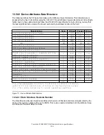
D8h

S.M.A.R.T. Enable Operations

D9h

S.M.A.R.T. Disable Operations

Dah

S.M.A.R.T. Return Status

Dbh

S.M.A.R.T. Enable/Disable Automatic Off-line

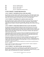
13.32.1 S.M.A.R.T. Function Subcommands

13.32.1.1 S.M.A.R.T. Read Attribute Values (subcommand D0h)

This subcommand returns the device's Attribute Values to the host. Upon receipt of the S.M.A.R.T. Read
Attribute Values subcommand from the host, the device asserts BSY, saves any updated Attribute Values
to the Attribute Data sectors, asserts DRQ, clears BSY, asserts INTRQ, and then waits for the host to
transfer the 512 bytes of Attribute Value information from the device via the Data Register.

13.32.1.2 S.M.A.R.T. Read Attribute Thresholds (subcommand D1h)

This subcommand returns the device's Attribute Thresholds to the host. Upon receipt of the S.M.A.R.T.
Read Attribute Thresholds subcommand from the host, the device asserts BSY, reads the Attribute
Thresholds from the Attribute Threshold sectors, asserts DRQ, clears BSY, asserts INTRQ, and then
waits for the host to transfer the 512 bytes of Attribute Thresholds information from the device via the Data
Register.

13.32.1.3 S.M.A.R.T. Enable/Disable Attribute Autosave (subcommand D2h)

This subcommand enables and disables the attribute auto save feature of the device. The S.M.A.R.T.
Enable/Disable Attribute Autosave subcommand allows the device to automatically save its updated
Attribute Values to the Attribute Data Sector at the timing of the first transition to Active idle mode and after
30 minutes after the last saving of Attribute Values. This subcommand causes the auto save feature to be
disabled. The state of the Attribute Autosave feature—either enabled or disabled—will be preserved by
the device across the power cycle.

A value of 00h—written by the host into the device's Sector Count Register before issuing the S.M.A.R.T.
Enable/Disable Attribute Autosave subcommand—will cause this feature to be disabled. Disabling this
feature does not preclude the device from saving Attribute Values to the Attribute Data sectors during
some other normal operation such as during a power-up or a power-down.

A value of F1h—written by the host into the device's Sector Count Register before issuing the S.M.A.R.T.
Enable/Disable Attribute Autosave subcommand—will cause this feature to be enabled. Any other
non-zero value written by the host into this register before issuing the S.M.A.R.T. Enable/Disable Attribute
Autosave subcommand will not change the current Autosave status. The device will respond with the error
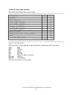
code specified in Figure 120 on page 175.

The S.M.A.R.T. Disable Operations subcommand disables the auto save feature along with the device's
S.M.A.R.T. operations.

Upon the receipt of the subcommand from the host, the device asserts BSY, enables or disables the
Autosave feature, clears BSY, and asserts INTRQ.

13.32.1.4 S.M.A.R.T. Save Attribute Values (subcommand D3h)

This subcommand causes the device to immediately save any updated Attribute Values to the device's
Attribute Data sector regardless of the state of the Attribute Autosave feature. Upon receipt of the
S.M.A.R.T. Save Attribute Values subcommand from the host, the device asserts BSY, writes any updated
Attribute Values to the Attribute Data sector, clears BSY, and asserts INTRQ.

Travelstar 32GH/30GT/20GN hard disk drive specifications

160

Содержание DJSA-210 - Travelstar 10 GB Hard Drive

Страница 1: ...M Hard disk drive specifications Travelstar 32GH 30GT 20GN 2 5 inch ATA IDE hard disk drive DJSA 220 DJSA 205 DJSA 230 DJSA 210 DJSA 232 Models Revision 4 0 7 December 2001 S07N 3499 05 Publication 15...

Страница 2: ...This page intentionally left blank...

Страница 3: ...ions Travelstar 32GH 30GT 20GN 2 5 inch ATA IDE hard disk drive DJSA 220 DJSA 205 DJSA 230 DJSA 210 DJSA 232 Models Revision 4 0 7 December 2001 S07N 3499 05 Publication 1520 IBM storage products offi...

Страница 4: ...itions of the publication IBM may make improvements and or changes in the product s and or the program s described in this publication at any time It is possible that this publication may contain refe...

Страница 5: ...very 20 5 5 Data buffer test 20 5 4 WRITE safety 19 5 3 Equipment status 19 5 2 Write Cache 19 5 1 Data loss on power off 19 5 0 Data integrity 16 4 5 3 Operating modes 14 4 5 2 Mechanical positioning...

Страница 6: ...Signal definitions 41 7 2 Interface connector 41 7 1 Cabling 41 7 0 Electrical interface specifications 39 6 11 Packaging 39 6 10 5 Secondary circuit protection 39 6 10 4 Flammability 39 6 10 3 Germa...

Страница 7: ...ure 79 11 5 7 Initial Power Mode at Power On 78 11 5 6 Interface Capability for Power Modes 78 11 5 5 Status 78 11 5 4 Standby timer 78 11 5 3 Standby Sleep command completion timing 77 11 5 2 Power m...

Страница 8: ...Native Max ADDRESS F8h 132 13 15 Read Multiple C4h 130 13 14 Read Long 22h 23h 128 13 13 Read DMA C8h C9h 127 13 12 Read Buffer E4h 126 13 11 Initialize Device Parameters 91h 125 13 10 Idle Immediate...

Страница 9: ...nds Support Coverage 189 15 0 Appendix 187 14 0 Time out values 185 13 40 Write Verify 3Ch vendor specific 184 13 39 Write Sectors 30h 31h 182 13 38 Write Multiple C5h 180 13 37 Write Long 32h 33h 178...

Страница 10: ...This page intentionally left blank...

Страница 11: ...Swept sine vibration 34 Figure 26 Random vibration PSD profile breakpoints operating 32 Figure 25 Mounting hole locations of the DJSA 232 230 31 Figure 24 Mounting hole locations of the DJSA 220 210...

Страница 12: ...1 of 7 114 Figure 78 Identify Device command ECh 113 Figure 77 Format Unit command F7h 112 Figure 76 Format track data field format 111 Figure 75 Format Track command 50h 110 Figure 74 Flush Cache com...

Страница 13: ...ual Threshold Data Structure 169 Figure 114 Device Attribute Thresholds Data Structure 166 Figure 113 Status Flag definitions 165 Figure 112 Individual Attribute Data Structure 164 Figure 111 Device A...

Страница 14: ...This page intentionally left blank...

Страница 15: ...000 000 bytes GB 1 000 000 000 bits Gb gravity a unit of force G field replacement unit FRU Federal Communications Commission FCC electrostatic discharge ESD Error Recovery Procedure ERP electromagne...

Страница 16: ...POH Programmed Input Output PIO Open Drain OD Output O oscillations per minute oct min number No or microsecond us millisecond ms millimeter mm Machine Level Control MLC megahertz MHz 1 000 00 bits pe...

Страница 17: ...hing hole on the top cover See Figure 1 on page 4 Do not touch the interface connector pins or the surface of the printed circuit board The drive can be damaged by shock or ESD Electric Static Dischar...

Страница 18: ...1 4 Drive handling precautions Do not press on the drive cover during handling Figure 1 Drive handling precautions Travelstar 32GH 30GT 20GN hard disk drive specifications 4...

Страница 19: ...e fly correction Segmented Buffer with write cache 2 MB Upper 174KB is used for firmware DJSA 232 230 220 512 KB Upper 128KB is used for firmware DJSA 210 205 Fast data transfer rate up to 66 6 MB sec...

Страница 20: ...perating Shock 150 G 2 ms DJSA 232 175 G 2 ms DJSA 230 220 210 205 Address Offset Feature to support DFT implementation Note Mounting screw position is incompatible with DBOA DMCA DCRA DSOA DPRA model...

Страница 21: ...Part 1 Functional specification Travelstar 32GH 30GT 20GN hard disk drive specifications 7...

Страница 22: ...This page intentionally left blank...

Страница 23: ...vo No ID formatting Multizone recording Code 32 34 ECC on the fly Enhanced Adaptive Battery Life Extender 3 2 Head disk assembly data The following technologies are used in each DJSA XXX model Pico Sl...

Страница 24: ...This page intentionally left blank...

Страница 25: ...fault logical drive parameters 4 2 Formatted capacity by model number 5 000 970 240 10 056 130 560 20 003 880 960 30 005 821 440 32 003 112 960 Total Logical Data Bytes 9 767 520 19 640 880 39 070 080...

Страница 26: ...968 21247 14 340 18688 19967 288 18944 19967 13 360 16896 18687 298 17408 18943 12 380 15616 16895 320 15616 17407 11 400 13568 15615 336 13568 15615 10 420 12032 13567 352 12288 13567 9 440 10752 120...

Страница 27: ...ives a typical value for each parameter The detail descriptions are found in section 5 0 16 6 66 6 16 6 66 6 16 6 66 6 Buffer host data transfer MB s PIO Mode 4 Ultra DMA Mode 4 109 203 109 203 120 22...

Страница 28: ...or to the start of a reliable read or write operation A reliable read or write operation implies that error correction recovery is not employed to cor rect arrival problems The Average Seek Time is me...

Страница 29: ...5400 DJSA 232 Average Latency ms Time 1 revolution ms Rotational Speed RPM Model Figure 10 Latency time 4 5 2 5 Drive ready time 9 5 3 0 DJSA 220 210 205 Power On To Ready 9 5 3 3 DJSA 230 Power On To...

Страница 30: ...position The spindle motor is rotating at full speed Standby The device interface is capable of accepting commands The spindle motor is stopped All circuitry but the host interface is in power saving...

Страница 31: ...tive Idle mode from Active Idle mode to Low Power Idle mode and from Low Power Idle mode to Standby mode is controlled adaptively according to the access pattern of the host system in order to reduce...

Страница 32: ...This page intentionally left blank...

Страница 33: ...s confirm the completion of the actual write operation prior to the power off by issuing a Soft reset Hard reset Flush Cache command Standby command Standby Immediate command Sleep command Confirm the...

Страница 34: ...y auto reallocation to the host system The conditions for auto reallocation are described below 5 7 1 Nonrecovered write errors When a write operation cannot be completed after the Error Recovery Proc...

Страница 35: ...the byte is bad On The Fly correctable Byte 0 1 2 3 4 5 6 7 8 9 0 1 2 3 4 5 6 7 1 1 1 1 1 1 1 1 Interleave A B C A B C A B C A B C A B C A B C A B C Error pattern 5 Error byte for each interleave X X...

Страница 36: ...This page intentionally left blank...

Страница 37: ...mum temperature gradient Altitude Nonoperating conditions 5 to 55 C See Note 8 to 90 noncondensing 29 4 C noncondensing 20 C hour 300 to 3048 m 10 000 ft Temperature Relative humidity Maximum wet bulb...

Страница 38: ...rk without degradation of the soft error rate under the following magnetic flux density limits at the enclosure surface 0 5 201 400 1 101 200 2 5 61 100 5 0 60 Limits Gauss RMS Frequency KHz Figure 17...

Страница 39: ...d average 0 65 0 65 0 9 Low Power Idle average 0 85 0 95 1 3 Active Idle average 3 1 85 1 85 2 0 Performance Idle average Notes DJSA 220 210 205 DJSA 230 DJSA 232 Watts RMS Typical Notes 1 The maximum...

Страница 40: ...Capacity GB Model Figure 19 Energy consumption efficiency Note Energy consumption efficiency is calculated as Power Consumption of Low Power Idle Watt Capacity GB 6 3 Startup current Figure 20 Typical...

Страница 41: ...Figure 21 Typical current wave form at start up of DJSA 230 Travelstar 32GH 30GT 20GN hard disk drive specifications 27...

Страница 42: ...tion The details are described in 11 7 S M A R T Function on page 80 and 13 32 S M A R T Function Set B0h on 159 6 4 3 Cable noise interference To avoid any degradation of performance throughput or er...

Страница 43: ...under the following assumptions Less than 333 power on hours per month Seeking Writing Reading operation is less than 20 of power on hours This does not represent any warranty or warranty period Appl...

Страница 44: ...ed system emergency unload is limited to rare scenarios such as battery removal during operation 6 4 6 3 Power switch design considerations In systems that use DJSA XXX consideration should be given t...

Страница 45: ...135 Max 100 2 0 25 69 85 0 25 12 5 0 2 DJSA 230 155 Max 100 2 0 25 69 85 0 25 12 5 0 2 DJSA 232 Weight gram Length mm Width mm Height mm Model Figure 23 Physical dimensions and weight 6 5 2 Mounting h...

Страница 46: ...axes 6 directions and will stay within the specified error rates when tilted 5 degrees from these positions Performance and error rate will stay within specification limits if the drive is operated i...

Страница 47: ...operation or spindle rotation 6 5 5 Load unload mechanism The head load unload mechanism is provided to protect the disk data during shipping movement or storage Upon power down a head unload mechani...

Страница 48: ...30 minutes of random vibration using the power spectral density PSD levels below The vibration test level is 0 67 G RMS Root Mean Square 5 0 x E 4 500 5 0 x E 4 200 1 0 x E 3 150 1 0 x E 3 65 8 0 x E...

Страница 49: ...00 to 10 Hz sine wave 0 5 oct min sweep rate 25 4 mm peak to peak displacement 5 to 10 to 5 Hz 6 6 3 Operating shock The hard disk drive meets the following criteria while operating in the conditions...

Страница 50: ...120 G 700 G DJSA 232 230 Duration of 11 ms Duration of 1 ms Model Figure 30 Nonoperating shock The shocks are applied for each direction of the drive for three mutually perpendicular axes one axis at...

Страница 51: ...cated 25 3 mm above from the chamber floor No sound absorbing material shall be used The acoustical characteristics of the disk drive are measured under the following conditions Mode definitions Idle...

Страница 52: ...mpatibility The drive when installed in a suitable enclosure and exercised with a random accessing routine at maximum data rate shall meet the following worldwide electromagnetic compatibility EMC req...

Страница 53: ...material with a UL recognized flammability rating of V 1 or better The flammability rating is marked or etched on the board All other parts not considered electrical components are made of material w...

Страница 54: ...This page intentionally left blank...

Страница 55: ...rs and Cable Assembly of the ATA ATAPI 5 document The figure below and Figure 6 5 2 on page 31 show the connector location and physical pin location 43 44 22 Pin Pin 19 1 2 A C B D Note 1 Pin position...

Страница 56: ...te I O DD07 03 GND 02 TTL I RESET 01 Type I O SIGNAL PIN Type I O SIGNAL PIN Notes 1 O designates an output from the Drive 2 I designates an input to the Drive 3 I O designates an input output common...

Страница 57: ...d from the Host address bus When active one of the Control Block Registers Alternate Status Device Control when written and Drive Address register can be selected RESET This line is used to reset the...

Страница 58: ...it is busy and has not yet passed its drive diagnostics If device 1 is present then device 0 shall wait up to 6 seconds from the receipt of a valid Execute Drive Diagnostics command for drive 1 to as...

Страница 59: ...a transfers between host and drive The signal HSTROBE is the data out strobe signal from the host for an Ultra DMA data out transfer Both the rising and falling edge of HSTROBE latch the data from DD...

Страница 60: ...urrent 2 4 V min 0 5 V max Output High Voltage Output Low Voltage Outputs 2 0 V min 5 5 V max 0 5 V min 0 8 V max Input High Voltage Input Low Voltage Inputs 7 6 Reset timings t10 t1 RESET BUSY 25 RES...

Страница 61: ...to IORDY active tRD 10 DIOR DIOW to address valid hold t9 30 Address valid to IOCS16 released t8 40 Address valid to IOCS16 assertion t7 30 DIOR data tristate t6z 5 DIOR data hold t6 20 DIOR data setu...

Страница 62: ...elay DIOW to DMARQ delay tLR tLW 25 DIOR negated pulse width DIOW negated pulse width tKR tKW 5 DIOR DIOW to DMACK hold tJ 0 DMACK to DIOR DIOW setup tI 10 DIOW data hold tH 20 DIOR DIOW data setup tG...

Страница 63: ...assert tZAD 10 10 10 10 10 Maximum time allowed for output drivers to release tAZ 57 86 115 154 230 Two cycle time t2CYC 25 39 54 73 112 Cycle time tCYC 120 0 130 0 170 0 200 0 230 0 First DSTROBE ti...

Страница 64: ...MAX ns MIN ns MAX ns MIN ns MAX ns MIN ns MAX ns MIN ns MAX ns MIN ns MODE 4 MODE 3 MODE 2 MODE 1 MODE 0 PARAMETER DESCRIPTION Note When a host does not satisfy the tSR timing the host should be ready...

Страница 65: ...e at device tDS 20 20 20 20 20 Interlock time with minimum tMLI 20 20 20 20 20 Minimum delay time required for output tZAH 10 10 10 10 10 Maximum time allowed for output drivers to release tAZ 100 0 1...

Страница 66: ...setup time at device tDS 20 20 20 20 20 Interlock time with minimum tMLI 20 20 20 20 20 Maximum delay time required for output tZAH 10 10 10 10 10 Maximum time allowed for output drivers to release tA...

Страница 67: ...me t2CYC 25 39 54 73 112 Cycle time tCYC 100 0 100 0 150 0 150 0 150 0 Limited interlock time tLI 0 0 0 0 0 Minimum time before driving IORDY tZIORDY 55 20 55 20 70 20 70 20 70 20 Envelope time tENV 2...

Страница 68: ...ns MIN ns MAX ns MIN ns MAX ns MIN ns MAX ns MIN ns MAX ns MIN ns MODE 4 MODE 3 MODE 2 MODE 1 MODE 0 PARAMETER DESCRIPTION Note When a device does not satisfy the tSR timing the device is ready to rec...

Страница 69: ...ld time at device tDH 5 7 7 10 15 CRC word setup time at device tDS 20 20 20 20 20 Interlocking time with minimum tMLI 100 0 100 0 150 0 150 0 150 0 Limited interlock time tLI 100 100 100 125 160 Read...

Страница 70: ...5 CRC word hold time at device tDH 5 7 7 10 15 CRC word setup time at device tDS 20 20 20 20 20 Interlock time with minimum tMLI 100 0 100 0 150 0 150 0 150 0 Limited interlock time tLI 50 50 50 50 5...

Страница 71: ...8 is ground or low the drive is a Master If pin 28 is open or logic high the drive is a Slave 1 2 3 4 5 3 1 4 2 1 Device 0 Master 2 Device 1 Slave 3 Cable Select 4 Never attach a jumper here 5 Never a...

Страница 72: ...rol Block registers The following table shows the I O address map Drive address Reg 1 1 1 0 1 Device control Reg Alt Status Reg 0 1 1 0 1 Control Block Registers Command Reg Status Reg 1 1 1 1 0 Drive...

Страница 73: ...Part 2 Interface specification Travelstar 32GH 30GT 20GN hard disk drive specifications 59...

Страница 74: ...This page intentionally left blank...

Страница 75: ...andards or newer standards S M A R T Error Logging and Self Test commands Ultra DMA 66 transfer commands DJSA XXX drives support the following functions as Vendor Specific Functions Address Offset Fea...

Страница 76: ...This page intentionally left blank...

Страница 77: ...the prefailure attributes exceed their corresponding thresholds For example a Power On Hours Attribute never results in a negative reliability status S M A R T Return Status WRITE VERIFY command does...

Страница 78: ...This page intentionally left blank...

Страница 79: ...a bus high imped x 0 1 A N Not used Data bus high imped x x 0 A N Control block registers Not used Data bus high imped x x x N N WRITE DIOW READ DIOR DA0 DA1 DA2 CS1 CS0 Functions Addresses x Does not...

Страница 80: ...efore writing to the Command Register 10 3 Cylinder High Register This register contains the high order bits of the starting cylinder address for any disk access At the end of the command this registe...

Страница 81: ...is in the Status Register 10 6 Device Control Register 0 0 1 IEN 2 SRST 3 1 4 5 6 7 Device Control Register Figure 50 Device Control Register Bit Definitions Interrupt Enable When IEN 0 and the devic...

Страница 82: ...is bit is not a device and will always be in a high impedance state HIZ 10 8 Device Head Register HS0 HS1 HS2 HS3 DRV 1 L 1 0 1 2 3 4 5 6 7 Device Head Register Figure 52 Device Head Register This reg...

Страница 83: ...ter ABRT ABT ID Not Found When IDN 1 it indicates that the requested sector s ID field could not be found IDNF IDN Uncorrectable Data Error When UNC 1 it indicates that an uncorrectable data error has...

Страница 84: ...Register continuously Therefore the host should not attempt to use IDX bit for timing purposes IDX Corrected Data Corrected Data is always 0 CORR COR Data Request Bit DRQ 1 indicates that the device i...

Страница 85: ...Soft Reset Software Reset The RESET signal is negated in the ATA Bus The device resets the interface circuitry and sets the default values Hard Reset Hardware Reset The device executes a series of ele...

Страница 86: ...ice operation o o Aborting Host interface soft reset hard reset POR o execute x not execute Note 1 Execute after the data in write cache has been written 2 The default value on POR is shown in Figure...

Страница 87: ...re 56 Default Register Values As a result of carrying out an Execute Device Diagnostic command or being powered on or if a hard reset occurs the system generates an Error Register diagnostic code See...

Страница 88: ...t DASP is asserted by Device 0 and Device 1 if it is present in order to indicate device active Soft Reset DASP is read by Device 0 to determine if Device 1 is present If Device 1 is present Device 0...

Страница 89: ...that load unload is operated normally NOT in emergency mode 11 3 2 Emergency unload When HDD power is interrupted while the heads are still loaded the microcode cannot operate and the normal 5V power...

Страница 90: ...ives support both Logical CHS Addressing Mode and LBA Addressing Mode as the sector addressing mode The host system may select either the currently selected CHS translation addressing or LBA addressin...

Страница 91: ...power consumption modes DJSA XXX implements the following set of functions 1 A Standby timer 2 Idle command 3 Idle Immediate command 4 Sleep command 5 Standby command 6 Standby Immediate command 11 5...

Страница 92: ...rammed period of inactivity If the device is in the active or idle mode the device waits for the specified time period and if no command is received the device automatically enters the standby mode If...

Страница 93: ...d power management levels contain discrete bands described in the section of Set Feature command in detail This feature set uses the following functions A SET FEATURES subcommand to enable Advanced Po...

Страница 94: ...sophisticated data analysis algorithms to predict the likelihood of near term degradation or fault condition By alerting the host system of a negative reliability status condition the host system can...

Страница 95: ...ibute thresholds then the device reliability status is negative indicating an impending degrading or faulty condition 11 7 5 S M A R T commands The S M A R T commands provide access to attribute value...

Страница 96: ...ord should be given or changed by a system user When the User Password is set the device enables the Device Lock Function and then the device is locked on the next power on reset or hard reset User Pa...

Страница 97: ...he next time the device is powered on Setting password POR Set Password with User Password Normal operation Power off Device locked mode POR Ref No setting password POR Normal operation Power off Devi...

Страница 98: ...assword Erase Unit Password Match Reject Complete Complete Erase Unit Lock function Disable Normal operation All commands are available Freeze Lock command Enter Device Frozen mode Normal Operation ex...

Страница 99: ...EMD with Master Password Normal operation Figure 63 Password lost 11 8 5 5 Attempt limit for the SECURITY UNLOCK command The SECURITY UNLOCK command has an attempt limit which helps to prevent a user...

Страница 100: ...alibrate o o x Read Verify Sector s w retry o o x Read Verify Sector s w o retry o o x Read Sector s w retry o o x Read Sector s w o retry o o o Read Native Max ADDRESS o o x Read Multiple o o x Read...

Страница 101: ...R T Return Status o o o S M A R T Read Attribute Thresholds o o o S M A R T Read Attribute Values o o o S M A R T Execute Off line Immediate o o o S M A R T Enable Operations o o o S M A R T Enable Di...

Страница 102: ...haracteristics 0FC000h to 0FFFFFh LBA range for protected area 1 032 192 0FC000h Customer usable sector count 528 482 304 byte 528MB Customer usable device size 16 384 004000h Required blocks for prot...

Страница 103: ...rotected area from remaining accessible Read information data from protected area Issue hard reset or POR to inhibit any access to the protected area 11 9 2 Set Max security extension commands The Set...

Страница 104: ...eturns command aborted until a power cycle The Set Max FREEZE LOCK command allows the host to disable the SET MAX commands including Set Max UNLOCK until the next power cycle When this command is acce...

Страница 105: ...ce wraps around so that the entire disk drive address space remains addressable in offset mode The Set Max pointer is set to the end of the reserved area to protect the data in the user area when oper...

Страница 106: ...es Enable Address Offset Mode command the command fails with Abort error status Disable Address Offset Feature removes the address offset and sets the size of the drive reported by the Identify Device...

Страница 107: ...s the original native maximum LBA are rejected with error even if the access protection is removed by a Set Max Address command Read Look Ahead operation is not carried out even if it is enabled by th...

Страница 108: ...st However actual seek operation for the next seek command starts right after completion of the actual seek operation for the first seek command The execution of two seek commands overlaps excluding t...

Страница 109: ...y command except the Write command is issued the operation to write the data from the cache buffer into the media is begun Power consumption can be reduced by Delayed Write When Write commands come wi...

Страница 110: ...eted after the Error Recovery Procedure ERP is fully carried out the sector s are reallocated to the spare location An error is reported to the host system only when the write cache is disabled and th...

Страница 111: ...red when the host reads the Status Register issues a reset or writes to the Command Register Figure 128 on page 187 shows the device time out values 12 1 Data In commands These commands are Identify D...

Страница 112: ...rror Register and interrupt the host The registers will contain the location of the sector in error The error location will be reported using CHS mode or LBA mode The mode is decided by the mode selec...

Страница 113: ...t has received the sector d After processing the sector of data the device sets BSY 0 and interrupts the host e In response to the interrupt the host reads the Status Register f The device clears the...

Страница 114: ...Return Status S M A R T Save Attribute Values Standby Standby Immediate Execution of these commands involves no data transfer 1 The host writes any required parameters to the Features Sector Count Se...

Страница 115: ...ts the DMA channel prior to reading status from the device The DMA protocol allows high performance multitasking operating systems to eliminate processor overhead associated with PIO transfers 1 The h...

Страница 116: ...This page intentionally left blank...

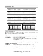
Страница 117: ...ADDRESS 3 1 1 0 0 0 1 0 0 C4 Read Multiple 1 0 0 1 0 0 0 1 1 23 Read Long no retry 1 0 0 1 0 0 0 1 0 22 Read Long retry 0 1 1 1 0 0 1 0 0 E4 Read Buffer 1 0 0 0 0 0 0 0 0 00 NOP 3 1 1 0 0 1 0 0 1 C9...

Страница 118: ...Read Log Sector 1 1 0 1 1 0 0 0 0 B0 S M A R T Read Attribute Thresholds 1 1 0 1 1 0 0 0 0 B0 S M A R T Read Attribute Values 1 1 0 1 1 0 0 0 0 B0 S M A R T Execute Off line Immediate 3 1 0 1 1 0 0 0...

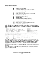
Страница 119: ...Enable Disable Automatic Off line DA B0 S M A R T Return Status D9 B0 S M A R T Disable Operations D8 B0 S M A R T Enable Operations D6 B0 S M A R T Write Log Sector D5 B0 S M A R T Read Log Sector D...

Страница 120: ...d by Set Max ADDRESS command V Valid This indicates that the bit is part of an output parameter and should be specified x This indicates that the hex character is not used This indicates that the bit...

Страница 121: ...DX COR DRQ DSC DF RDY BSY AMN T0N ABT 0 IDN 0 UNC CRC 0 1 2 3 4 5 6 7 0 1 2 3 4 5 6 7 Status Register Error Register Figure 71 Check Power Mode command E5h 98h The Check Power Mode command will report...

Страница 122: ...ster Error Register Figure 72 Enable Disable Delayed Write command FAh The Enable Disable Delayed Write command sets if the Delayed Write function is enabled or disabled Delayed Write function is enab...

Страница 123: ...V V V V V V 0 ERR IDX COR DRQ DSC DF RDY BSY AMN T0N ABT 0 IDN 0 UNC CRC 0 1 2 3 4 5 6 7 0 1 2 3 4 5 6 7 Status Register Error Register Figure 73 Execute Device Diagnostic command 90h The Execute Dev...

Страница 124: ...t Registers V 0 V 0 V 0 0 0 V 0 0 0 0 0 ERR IDX COR DRQ DSC DF RDY BSY AMN T0N ABT 0 IDN 0 UNC CRC 0 1 2 3 4 5 6 7 0 1 2 3 4 5 6 7 Status Register Error Register Figure 74 Flush Cache command E7h This...

Страница 125: ...rack will be lost The host transfers a sector of data containing a format table to the device The format table should contain two bytes for each sector on the track to be formatted The structure of th...

Страница 126: ...The descriptor value does not match the certain value except 00h In LBA mode this command formats a single logical track including the specified LBA Explanation for descriptor Descriptor 00h This ind...

Страница 127: ...lable right after this command s completion This commands completion is also used on the next power on reset or hard reset Both previous information data are erased from the device by this command Not...

Страница 128: ...elow Error Feature Data Data 7 6 5 4 3 2 1 0 Register 7 6 5 4 3 2 1 0 Register Command Block Input Registers Command Block Output Registers V 0 0 V 0 0 0 V 0 0 0 0 0 ERR IDX COR DRQ DSC DF RDY BSY AMN...

Страница 129: ...equired to spin up and IDENTIFY DEVICE response is complete C837H 02 Number of cylinders in default translate mode Note1 01 Reserved 0 0 1 hard sectored 1 1 1 identify data incomplete 2 0 1 not MFM en...

Страница 130: ...the word 15 3 0 Reserved 2 1 1 Word 88 is Valid 1 1 1 Word 64 70 are Valid 0 1 1 Word 54 58 are Valid XXX7H 53 DMA data transfer cycle timing mode Refer Word 62 and 63 0200H 52 PIO data transfer cycle...

Страница 131: ...ATAPI 5 003CH 80 Reserved 0000H 69 79 Minimum PIO Transfer Cycle Time WithIORDY Flow Control 15 0 78 Cycle time in nanoseconds 120ns 16 6MB s 0078H 68 Minimum PIO Transfer Cycle Time Without Flow Cont...

Страница 132: ...R T Feature Set enabled F4XXH 85 Command set feature supported extension 15 0 Always 14 1 Always 13 0 0 Reserved 4000H 84 Command set supported 15 0 Always 14 1 Always 13 9 0 Reserved 8 1 1 SET MAX s...

Страница 133: ...MA mode 2 is supported 1 1 1 UltraDMA mode 1 is supported 0 1 1 UltraDMA mode 0 is supported XX1FH 88 Command set feature enabled 15 0 Always 14 1 Always 13 0 0 Reserved 4000H 87 Command set feature e...

Страница 134: ...ce 1 passed diagnostic 10 9 X how Device 1 determined the device number 00 Reserved 01 a jumper was used 10 the CSEL signal was used 11 some other method was used or the method is unknown 8 1 Always 7...

Страница 135: ...Power Mode 1 Standby 0 Idle 000XH 131 Reserved XXXXH 130 Current Set Feature Option Bit assignments 15 4 0 Reserved 3 X 1 Auto reassign enabled 2 X 1 Reverting enabled 1 X 1 Read Look ahead enabled 0...

Страница 136: ...h Number of heads 3FFFh Number of cylinders DJSA 220 37E3E40h Total number of user addressable sectors IBM DJSA 230 Model number ASCII 0EA5h 1874 KB Buffer size 10h Number of heads 3FFFh Number of cyl...

Страница 137: ...ters Command Block Output Registers V 0 0 V 0 0 0 V 0 0 0 0 0 ERR IDX COR DRQ DSC DF RDY BSY AMN T0N ABT 0 IDN 0 UNC CRC 0 1 2 3 4 5 6 7 0 1 2 3 4 5 6 7 Status Register Error Register Figure 81 Identi...

Страница 138: ...tandby timer the point timer starts counting down When the Idle mode is entered the device is spun up to operating speed If the device is already spinning the spin up sequence is not executed During I...

Страница 139: ...0 ERR IDX COR DRQ DSC DF RDY BSY AMN T0N ABT 0 IDN 0 UNC CRC 0 1 2 3 4 5 6 7 0 1 2 3 4 5 6 7 Status Register Error Register Figure 83 Idle Immediate command E1h 95h The Idle Immediate command causes...

Страница 140: ...evice Parameters command enables the host to set the number of sectors per track and the number of heads minus 1 per cylinder Words 54 58 in Identify Device Information reflects these parameters The p...

Страница 141: ...RDY BSY AMN T0N ABT 0 IDN 0 UNC CRC 0 1 2 3 4 5 6 7 0 1 2 3 4 5 6 7 Status Register Error Register Figure 85 Read Buffer command E4h The Read Buffer command transfers a sector of data from the sector...

Страница 142: ...ferred through the Data Register 16 bits at a time The host initializes a slave DMA channel prior to issuing the command The data transfers are qualified by the DMARQ and are performed by the slave DM...

Страница 143: ...ess an unrecoverable error occurs Sector Number This indicates the sector number of the last transferred sector L 0 In LBA mode this register contains the current LBA bits 0 7 L 1 Cylinder High Low Th...

Страница 144: ...he device will keep setting DRQ 1 to indicate that the device is ready to transfer the ECC bytes to the host The data is transferred 16 bits at a time and the ECC bytes are transferred 8 bits at a tim...

Страница 145: ...number of the transferred sector L 0 In LBA mode this register contains current LBA bits 8 15 Low 16 23 High L 1 H This indicates the head number of the transferred sector L 0 In LBA mode this registe...

Страница 146: ...rs the data from the device to the host The sectors are transferred through the Data Register 16 bits at a time The command execution is identical to the Read Sectors command with one exception an int...

Страница 147: ...r L 0 In LBA mode this register contains the current LBA bits 0 7 L 1 Cylinder High Low This indicates the cylinder number of the last transferred sector L 0 In LBA mode this register contains the cur...

Страница 148: ...ax ADDRESS command Even if the Address Offset mode is enabled the native max LBA CYL of HDD is returned Output Parameters To The Device L LBA mode This indicates the addressing mode An L 0 specifies C...

Страница 149: ...the CHS mode this register contains the native maximum head number L 0 V Valid Indicates that the bit is part of an input parameter and will be set to 0 or 1 by the device This indicates that the bit...

Страница 150: ...from disk media and then transfers the data from the device to the host The sectors are transferred through the Data Register 16 bits at a time If an uncorrectable error occurs the read will be termin...

Страница 151: ...L 0 In LBA mode this register contains the current LBA bits 0 7 L 1 Cylinder High Low This is the cylinder number of the last transferred sector L 0 In LBA mode this register contains the current LBA...

Страница 152: ...rs command verifies one or more sectors on the device No data is transferred to the host The difference between the Read Sectors command and Read Verify Sectors command is data is transferred to the h...

Страница 153: ...an unrecoverable error occurs Sector Number This is the sector number of the last transferred sector L 0 In LBA mode this register contains the current LBA bits 0 7 L 1 Cylinder High Low This is the c...

Страница 154: ...Block Input Registers Command Block Output Registers V 0 V 0 V 0 0 V V 0 0 0 0 0 ERR IDX COR DRQ DSC DF RDY BSY AMN T0N ABT 0 IDN 0 UNC CRC 0 1 2 3 4 5 6 7 0 1 2 3 4 5 6 7 Status Register Error Regis...

Страница 155: ...g information specified in Figure 93 Then the device checks the transferred password If the User Password or Master Password matches the given password the device disables the security mode feature de...

Страница 156: ...0 0 0 0 ERR IDX COR DRQ DSC DF RDY BSY AMN T0N ABT 0 IDN 0 UNC CRC 0 1 2 3 4 5 6 7 0 1 2 3 4 5 6 7 Status Register Error Register Figure 95 Security Erase Prepare command F3h The Security Erase Prepa...

Страница 157: ...t command initializes all user data sectors and then disables the device lock function Note that the Security Erase Unit command initializes from LBA 0 to Native MAX LBA The Host MAX LBA is set by the...

Страница 158: ...prepare command should be completed immediately prior to the Security Erase Unit command If the device receives a Security Erase Unit command without a prior Security Erase Prepare command the device...

Страница 159: ...N T0N ABT 0 IDN 0 UNC CRC 0 1 2 3 4 5 6 7 0 1 2 3 4 5 6 7 Status Register Error Register Figure 98 Security Freeze Lock command F5h The Security Freeze Lock Command allows the device to enter frozen m...

Страница 160: ...and F1h The Security Set Password command enables the security mode feature device lock function and sets the master password or the user password The security mode feature device lock function is ena...

Страница 161: ...de field is set with Master password If Identifier is User the Revision Code is not set The Revision Code field is returned in the Identify Device word 92 The valid Revision Codes are 0000h to FFFDh T...

Страница 162: ...ntifier Master Security level Maximum This combination will set a master password but will NOT enable the security mode feature lock function Travelstar 32GH 30GT 20GN hard disk drive specifications 1...

Страница 163: ...he device will be in device lock mode The password has not been changed yet The Security Unlock command requests to transfer a single sector of data from the host including information specified in Fi...

Страница 164: ...the device regards Password as the Master Password The user can detect if the attempt to unlock the device has failed due to a mismatched password as this is the only reason that an abort error will b...

Страница 165: ...esignated track and selects the designated head The device does not need to be formatted for a seek to execute properly Output Parameters To The Device Sector Number In LBA mode this register specifie...

Страница 166: ...e 104 Sense Condition Command F0h The Sense Condition command is used to sense temparature in a device This command is executable winthout spinning up even if a device is started with No Spin Up optio...

Страница 167: ...ABT 0 IDN 0 UNC CRC 0 1 2 3 4 5 6 7 0 1 2 3 4 5 6 7 Status Register Error Register Figure 105 Set Features command EFh The Set Feature command establishes the following parameters which affect the ex...

Страница 168: ...Flow Control Transfer Mode x 00001 nnn 00000 001 PIO Default Transfer Mode Disable IORDY 00000 000 PIO Default Transfer Mode When the Feature register is 05h Enable Advanced Power Management the Secto...

Страница 169: ...which is set via this command as a default value This command implement SET MAX security extension commands as subcommands But regardless of Feature register value the case this command is immediatel...

Страница 170: ...bits 24 27 which are to be input L 1 In CHS mode this register is ignored L 0 L This indicates the LBA addressing mode L 0 specifies the CHS mode and L 1 specifies the LBA addressing mode D This indi...

Страница 171: ...es the device to perform Read and Write Multiple commands and establishes the block size for these commands The block size is the number of sectors to be transferred for each interrupt The default blo...

Страница 172: ...5 6 7 Status Register Error Register Figure 108 Sleep command E6h 99h This command is the only way to cause the device to enter Sleep Mode When this command is issued the device confirms the completi...

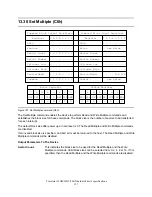
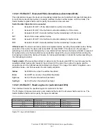
Страница 173: ...s the Attribute Thresholds and other low level subcommands that can be used for logging and reporting purposes and to accommodate special user needs The S M A R T Function Set command has several sepa...

Страница 174: ...ses the auto save feature to be disabled The state of the Attribute Autosave feature either enabled or disabled will be preserved by the device across the power cycle A value of 00h written by the hos...

Страница 175: ...outine and service the host within two seconds after receipt of the new command After servicing the interrupting command the device will resume its routine automatically or not start its routine depen...

Страница 176: ...s subcommand from the host the device asserts BSY disables S M A R T capabilities and functions clears BSY and asserts INTRQ After receipt of the device of the S M A R T Disable Operations subcommand...

Страница 177: ...ile memory during some other normal operation such as during a power on during a power off sequence or during an error recovery sequence A value of one written by the host into the device s Sector Cou...

Страница 178: ...ollection capability 2 1 16Eh 1 Current segment pointer 2 1 16Ch 2 Total time in seconds to complete off line data collection activity 2 1 16Bh 1 Self test execution status 2 1 16Ah 1 Off line data co...

Страница 179: ...rved may either 0 Bit 1 On line Collection Bit 0 Pre Failure Advisory bit flags 01h 2 Status Flags binary 00h 1 Attribute ID Number 01h to FFh Value Offset Byte Description Figure 112 Individual Attri...

Страница 180: ...ondition where imminent loss of data is being predicted Pre Failure Advisory bit 0 Definition Flag Name Bit Figure 113 Status Flag definitions Normalized values The device will perform conversion of t...

Страница 181: ...rcent increments Valid values are 0 through 9 4 7 Current Self test execution status 0 The self test routine completed without error or has never been run 1 The self test routine was aborted by the ho...

Страница 182: ...Read Scanning 1 The device supports Off line Read Scanning 4 Self test implemented bit 0 Self test routing is not implemented 1 Self test routine is implemented 5 7 Reserved 0 13 32 2 8 S M A R T Capa...

Страница 183: ...tive Attribute Thresholds will appear in the same order as their corresponding Attribute Values 512 2 1FFh 1 Data structure checksum 00h 17Ch 131 Vendor specific 00h 16Ah 18 Reserved 2 1 15Eh 12 30th...

Страница 184: ...ata Structure 13 32 3 3 Attribute ID Numbers Attribute ID Numbers supported by the device are the same as Attribute Values Data Structures 13 32 3 4 Attribute Threshold These values are preset at the...

Страница 185: ...B6h 90 3rd error log data structure 5Ch 90 2nd error log data structure 02h 90 1st error log data structure 01h 1 Error log pointer 00h 1 S M A R T error log version Offset Byte Description Figure 116...

Страница 186: ...cription Figure 117 Error log data structure Command data structure Data format of each command data structure is shown below 12 08h 4 Time stamp milliseconds from Power On 07h 1 Command register 06h...

Страница 187: ...Sector number register 02h 1 Sector count register 01h 1 Error register 00h 1 Reserved Offset Byte Description Figure 119 Error data structure State field contains a value indicating the device state...

Страница 188: ...Self test execution status n 18h 02h 1 Self test number 00h 2 Data structure revision Offset Byte Description Figure 120 Self test log data structure The data structure contains the descriptor of the...

Страница 189: ...bcommand other than S M A R T ENABLE OPERATIONS was received by the device while the device was in a S M A R T Disabled state 04h 51h A S M A R T FUNCTION SET command was received by the device with a...

Страница 190: ...t asserts the INTRQ Following the INTRQ the interface remains active and the device is spun down If the device is already spun down the spin down sequence is not executed During the Standby mode the d...

Страница 191: ...gister Figure 123 Standby Immediate command E0h 94h The Standby Immediate command causes the device to enter the Standby mode immediately When this command is issued the device confirms the completion...

Страница 192: ...0 0 0 ERR IDX COR DRQ DSC DF RDY BSY AMN T0N ABT 0 IDN 0 UNC CRC 0 1 2 3 4 5 6 7 0 1 2 3 4 5 6 7 Status Register Error Register Figure 124 Write Buffer command E8h The Write Buffer command transfers a...

Страница 193: ...the disk media The sectors of data are transferred through the Data Register 16 bits at a time The host initializes a slave DMA channel prior to issuing the command Data transfers are qualified by DM...

Страница 194: ...d sectors not transferred The Sector Count will be zero unless an unrecoverable error occurs Sector NumberThis indicates the sector number of the last transferred sector L 0 In LBA mode this register...

Страница 195: ...the device then the data and the ECC bytes are written to the disk media After 512 bytes of data have been transferred the device will keep setting DRQ 1 to indicate that the device is ready to recei...

Страница 196: ...linder number of the sector to be transferred L 0 In LBA mode this register contains current the LBA bits 8 15 Low and bits 16 23 High L 1 H This indicates the head number of the sector to be transfer...

Страница 197: ...is written to the disk media Command execution is identical to the Write Sectors command except that an interrupt is generated for each block as defined by the Set Multiple command instead of for each...

Страница 198: ...sector L 0 In LBA mode this register contains current the LBA bits 0 7 L 1 Cylinder High Low This indicates the cylinder number of the last transferred sector L 0 In LBA mode this register contains th...

Страница 199: ...to the device The data is then written to the disk media The sectors are transferred through the Data Register 16 bits at a time If an uncorrectable error occurs the write will be terminated at the fa...

Страница 200: ...contains the current LBA bits 0 7 L 1 Cylinder High Low This indicates the cylinder number of the last transferred sector L 0 In LBA mode this register contains the current LBA bits 8 15 Low and bits...

Страница 201: ...ut Command 10 us Status Register BSY 1 256th Read From Data Register Device Busy After Data Transfer In 30 sec Status Register BSY 0 and DRQ 1 Interrupt Status Register BSY 1 Interrupt DRQ For Data Tr...

Страница 202: ...13 22 Security Erase Unit F4h on page 143 Note 2 For FORMAT UNIT command the execution time is referred to 13 6 Format Unit F7h Vendor Specific on page 113 Note 3 When the initial power mode at power...

Страница 203: ...RAMETERS 91h Mandatory Yes EXECUTE DEVICE DIAGNOSTIC 90h Optional No CFA TRANSLATE SECTORS 87h Mandatory Yes SEEK 7xh obsoleted Yes FORMAT TRACK 50h obsoleted Yes READ VERIFY SECTORS S w o retry 41h M...

Страница 204: ...SLEEP E6h Mandatory Yes CHECK POWER MODE E5h Optional Yes READ BUFFER E4h Mandatory Yes IDLE E3h Mandatory Yes STANDBY E2h Mandatory Yes IDLE IMMEDIATE E1h Mandatory Yes STANDBY IMMEDIATE E0h Optiona...

Страница 205: ...Disable Address Offset mode 89h Yes Disable Advanced Power Management 85h Yes Disable write cache 82h Yes Disable reverting to power on defaults 66h No Enable SERVICE interrupt 5Eh No Enable release i...

Страница 206: ...Travelstar 32GH 30GT 20GN hard disk drive specifications 192...

Страница 207: ...130 Read Multiple C4h 132 Read Native Max ADDRESS F8h 134 Read Sectors 20h 21h 136 Read Verify Sectors 40h 41h 138 Recalibrate 1xh 140 S M A R T Function Set B0h 158 Security Disable Password F6h 141...

Страница 208: ...s 20 96 O Operating modes 16 P Performance Idle mode 79 PIO timings 47 Power management 77 Power Management Feature Initial Power Mode at Power On 79 Interface Capability for Power Modes 78 Power Mana...

Страница 209: ...94 Service life and usage condition 29 Set Features 100 152 SET FEATURES Command Support Coverage 191 Set Max ADDRESS 100 154 Set Multiple 156 Set Multiple Mode 100 Shock 34 Single track seek time 15...

Страница 210: ...Reserved IBM is a registered trademark of International Business Machines Corporation Other company product and service names may be trademarks or service marks of others Product description data rep...

Страница 211: ......
Отзывы: