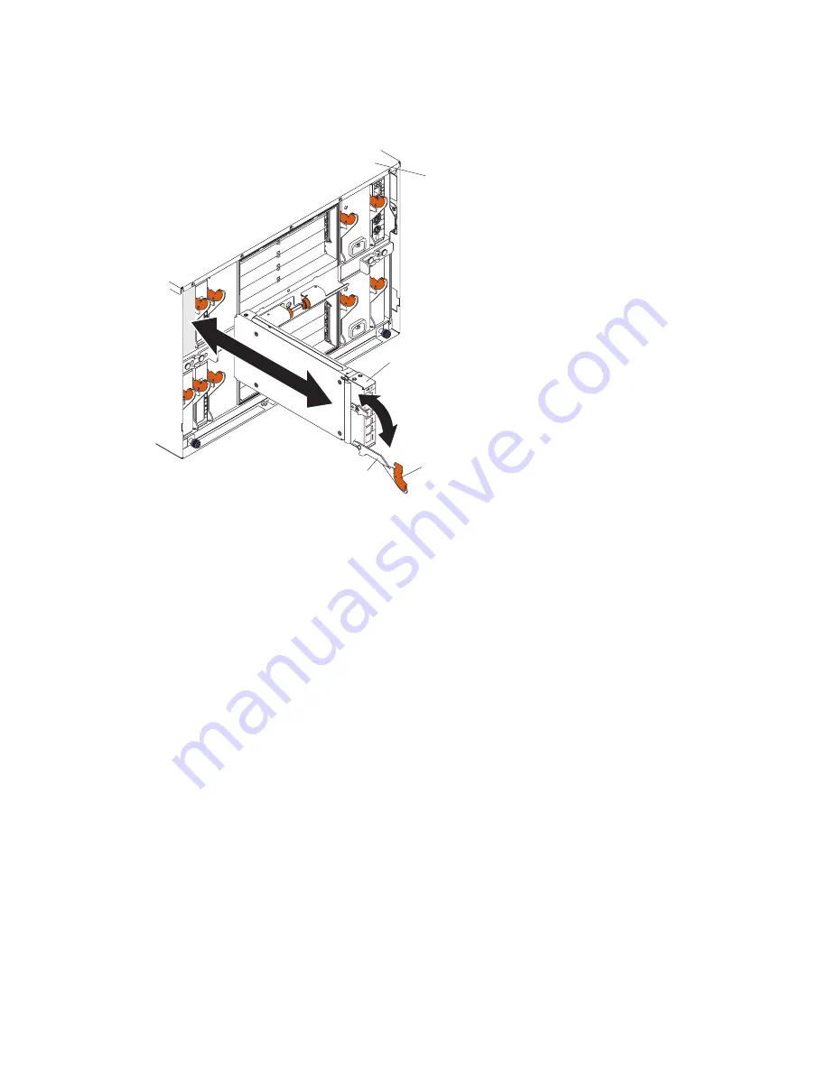
5.
Pull
the
release
latch
toward
the
bottom
of
the
switch
module
as
shown
in
the
following
illustration.
The
module
moves
out
of
the
bay
approximately
0.6
cm
(0.25
inch).
BladeCenter
unit
Latch
Release
lever
Fibre Channel
switch module
6.
Slide
the
switch
module
out
of
the
bay
and
set
it
aside.
7.
Place
either
another
switch
module
or
a
filler
module
in
the
bay.
Important
:
Complete
this
step
within
1
minute
(see
steps
9
and
10
on
page
16
for
more
information).
8.
If
you
placed
another
switch
module
into
the
bay
and
if
you
are
using
the
external
switch-module
ports,
insert
any
SFP
modules
that
you
removed
in
step
4
on
page
17
into
external
Fibre
Channel
port
0
and
Fibre
Channel
ports
15
through
19.
For
SFP-module
installation
instructions,
see
the
documentation
that
comes
with
the
SFP
module.
9.
Use
LC-LC
or
LC-SC
fiber-optic
cables
to
connect
the
switch-module
external
ports
to
external
Fibre
Channel
devices.
For
more
information,
see
the
documentation
that
comes
with
the
cable
options.
10.
Replace
the
acoustic
attenuation
module,
if
you
removed
it
in
step
2
on
page
17.
18
Brocade
4
Gb
SAN
Switch
Module:
Installation
Guide
Содержание BROCADE 4 GB FC HBAS
Страница 1: ...Brocade 4 Gb SAN Switch Module for IBM Eserver BladeCenter Installation Guide ...
Страница 2: ......
Страница 3: ...Brocade 4 Gb SAN Switch Module for IBM Eserver BladeCenter Installation Guide ...
Страница 12: ...x Brocade 4 Gb SAN Switch Module Installation Guide ...
Страница 36: ...24 Brocade 4 Gb SAN Switch Module Installation Guide ...
Страница 46: ...34 Brocade 4 Gb SAN Switch Module Installation Guide ...
Страница 50: ...38 Brocade 4 Gb SAN Switch Module Installation Guide ...
Страница 54: ...42 Brocade 4 Gb SAN Switch Module Installation Guide ...
Страница 78: ...66 Brocade 4 Gb SAN Switch Module Installation Guide ...
Страница 87: ......
Страница 88: ... Part Number 24R9711 Printed in USA 1P P N 24R9711 ...


