background image

(L008)

CAUTION: Hazardous moving parts nearby. (L008)

All lasers are certified in the U.S. to conform to the requirements of DHHS 21 CFR Subchapter J for class 1

laser products. Outside the U.S., they are certified to be in compliance with IEC 60825 as a class 1 laser

product. Consult the label on each part for laser certification numbers and approval information.

CAUTION: This product might contain one or more of the following devices: CD-ROM drive, DVD-

ROM drive, DVD-RAM drive, or laser module, which are Class 1 laser products. Note the following

information:
• Do not remove the covers. Removing the covers of the laser product could result in exposure to

hazardous laser radiation. There are no serviceable parts inside the device.

• Use of the controls or adjustments or performance of procedures other than those specified

herein might result in hazardous radiation exposure.

(C026)
CAUTION: Data processing environments can contain equipment transmitting on system links

with laser modules that operate at greater than Class 1 power levels. For this reason, never look

into the end of an optical fiber cable or open receptacle. Although shining light into one end and

looking into the other end of a disconnected optical fiber to verify the continuity of optic fibers may

not injure the eye, this procedure is potentially dangerous. Therefore, verifying the continuity of

optical fibers by shining light into one end and looking at the other end is not recommended. To

verify continuity of a fiber optic cable, use an optical light source and power meter. (C027)
CAUTION: This product contains a Class 1M laser. Do not view directly with optical instruments.

(C028)
CAUTION: Some laser products contain an embedded Class 3A or Class 3B laser diode. Note the

following information:
• Laser radiation when open.
• Do not stare into the beam, do not view directly with optical instruments, and avoid direct

exposure to the beam. (C030)

(C030)
CAUTION: The battery contains lithium. To avoid possible explosion, do not burn or charge the

battery.
Do Not:
• Throw or immerse into water
• Heat to more than 100 degrees C (212 degrees F)
• Repair or disassemble
Exchange only with the IBM-approved part. Recycle or discard the battery as instructed by local

regulations. In the United States, IBM has a process for the collection of this battery. For

information, call 1-800-426-4333. Have the IBM part number for the battery unit available when

you call. (C003)
CAUTION: Regarding IBM provided VENDOR LIFT TOOL:
• Operation of LIFT TOOL by authorized personnel only.

Safety notices  xi

Содержание 9040-MR9

Страница 1: ...Power Systems Memory modules for the 9040 MR9 IBM ...

Страница 2: ...l G229 9054 and the IBM Environmental Notices and User Guide Z125 5823 This edition applies to IBM Power Systems servers that contain the POWER9 processor and to all associated models Copyright International Business Machines Corporation 2018 2020 US Government Users Restricted Rights Use duplication or disclosure restricted by GSA ADP Schedule Contract with IBM Corp ...

Страница 3: ...rmanently removing a memory module 38 Memory riser 43 Installing a memory riser 43 Preparing the system to install a memory riser 43 Installing a memory riser 49 Preparing the system for operation after installing memory riser 51 Removing and replacing memory riser in the system 55 Preparing the system 55 Removing a memory riser 62 Replacing a memory riser 64 Preparing the system for operation 66 ...

Страница 4: ...iv ...

Страница 5: ...800 300 8751 German safety information Das Produkt ist nicht für den Einsatz an Bildschirmarbeitsplätzen im Sinne 2 der Bildschirmarbeitsverordnung geeignet Laser safety information IBM servers can use I O cards or features that are fiber optic based and that utilize lasers or LEDs Laser compliance IBM servers may be installed inside or outside of an IT equipment rack DANGER When working on or aro...

Страница 6: ...ices To Disconnect 1 Turn off everything unless instructed otherwise 2 For AC power remove the power cords from the outlets 3 For racks with a DC power distribution panel PDP turn off the circuit breakers located in the PDP and remove the power from the Customer s DC power source 4 Remove the signal cables from the connectors 5 Remove all cables from the devices To Connect 1 Turn off everything un...

Страница 7: ... devices that attach to the system It is the responsibility of the customer to ensure that the outlet is correctly wired and grounded to prevent an electrical shock R001 part 1 of 2 R001 part 2 of 2 CAUTION Do not install a unit in a rack where the internal rack ambient temperatures will exceed the manufacturer s recommended ambient temperature for all your rack mounted devices Do not install a un...

Страница 8: ...hazards Verify that the route that you choose can support the weight of the loaded rack cabinet Refer to the documentation that comes with your rack cabinet for the weight of a loaded rack cabinet Verify that all door openings are at least 760 x 230 mm 30 x 80 in Ensure that all devices shelves drawers doors and cables are secure Ensure that the four leveling pads are raised to their highest posit...

Страница 9: ...y position for example when working from a ladder Stability hazard The rack may tip over causing serious personal injury Before extending the rack to the installation position read the installation instructions Do not put any load on the slide rail mounted equipment mounted in the installation position Do not leave the slide rail mounted equipment in the installation position L002 L003 or or or Sa...

Страница 10: ...oduct might be equipped with multiple AC power cords or multiple DC power cables To remove all hazardous voltages disconnect all power cords and power cables L003 L007 CAUTION A hot surface nearby L007 x Power Systems Power Systems Memory ...

Страница 11: ...king into the other end of a disconnected optical fiber to verify the continuity of optic fibers may not injure the eye this procedure is potentially dangerous Therefore verifying the continuity of optical fibers by shining light into one end and looking at the other end is not recommended To verify continuity of a fiber optic cable use an optical light source and power meter C027 CAUTION This pro...

Страница 12: ...e on off smooth platforms without appreciable force so take care not to push or lean Keep riser tilt adjustable angling platform option flat at all times except for final minor angle adjustment when needed Do not stand under overhanging load Do not use on uneven surface incline or decline major ramps Do not stack loads Do not operate while under the influence of drugs or alcohol Do not support lad...

Страница 13: ...uitable for connection to intrabuilding or unexposed wiring or cabling only The intrabuilding ports of this equipment must not be metallically connected to the interfaces that connect to the OSP outside plant or its wiring These interfaces are designed for use as intrabuilding interfaces only Type 2 or Type 4 ports as described in GR 1089 CORE and require isolation from the exposed OSP cabling The...

Страница 14: ...xiv Power Systems Power Systems Memory ...

Страница 15: ...by the service provider for this service If your system is managed by the Hardware Management Console HMC use the HMC to complete the steps for installing a memory module in the system For instructions see Installing a part by using the HMC www ibm com support knowledgecenter POWER9 p9haj hmcinstall htm If your system is not managed by an HMC complete the steps in the following procedures to insta...

Страница 16: ...e working on For instructions see Identifying a part www ibm com support knowledgecenter POWER9 p9haj sal htm Use the blue identify LED on the enclosure to locate the system Ensure that the serial number of the system matches the serial number to be serviced 2 Stop the system For instructions see Stopping a system www ibm com support knowledgecenter POWER9 p9haj crustopsys htm 3 Label and disconne...

Страница 17: ...Figure 1 Removing the power cords L003 or or Memory modules for the 9040 MR9 3 ...

Страница 18: ...quipped with multiple AC power cords or multiple DC power cables To remove all hazardous voltages disconnect all power cords and power cables L003 5 Complete the following steps to place the system in the service position 4 Power Systems Power Systems Memory ...

Страница 19: ...llips screwdriver b Release the side latches B by pressing them downward as shown in the following figure c Pull out the system C as shown in the following figure Ensure that any cables do not catch or bind as you pull out the system Figure 2 Placing the system in service position 6 Attach the electrostatic discharge ESD wrist strap The ESD wrist strap must be connected to an unpainted metal surfa...

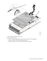
Страница 20: ... an unpainted metal surface of the system for a minimum of 5 seconds If at any point in this service process you move away from the system it is important to again discharge yourself by touching an unpainted metal surface for at least 5 seconds before you continue with the service process 7 Remove the service access cover Attention Operating the system without the service access cover on for more ...

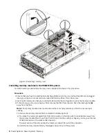
Страница 21: ... memory riser a Open the release latches A on the memory riser as shown in the following figure Open the latches to the fully upright 90 degree position b Pull out the memory riser from the slot by holding onto the latches Memory modules for the 9040 MR9 7 ...

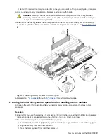
Страница 22: ...s a filler remove the filler from the slot Push the locking tabs A away from the filler Note The memory module slots must contain either a memory module or a filler to ensure proper cooling To remove the memory module filler complete the following steps a To unlock the memory module filler from its connector in the slot push the locking tabs away from the memory module filler If you find it hard t...

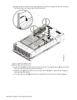
Страница 23: ...9 Figure 5 Installing memory modules in a memory riser 6 Repeat steps 2 on page 8 through 5 on page 9 for each memory module Preparing the 9040 MR9 system for operation after installing memory modules To prepare the system for operation after you install memory modules complete the steps in this procedure Procedure 1 Ensure that you have the electrostatic discharge ESD wrist strap on and that the ...

Страница 24: ...ss cover a Lower the cover A onto the system unit Ensure that the cover alignment pins C on each side of the cover fit into the matching slots in the chassis b Slide the cover A onto the system unit Ensure that the tabs D tuck under the mesh along the front opening of the chassis c Close the release latches B by pushing it in the direction that is shown in the following figure 10 Power Systems Pow...

Страница 25: ...ont as shown in the following figure b Push the system unit back into the rack as shown in the following figure until both release latches of the system unit lock into position Ensure that any cables do not catch or bind as you push in the system Note Slide the system unit slowly into the rack to ensure that your fingers do not get caught in the side rails Memory modules for the 9040 MR9 11 ...

Страница 26: ...e external cables that plug into the PCIe adapters 6 Using your labels reconnect the power cords A to the system unit as shown in the following figure Fasten the power cords to the system by using the hook and loop fasteners B as shown in the following figure 12 Power Systems Power Systems Memory ...

Страница 27: ...9haj p9haj_turn_off_identify_led htm 9 Verify the installed part If you replaced the part because of a service action verify the installed part For instructions see Verifying a repair www ibm com support knowledgecenter POWER9 p9ect pxect_verifyrepair htm If you installed the part for any other reason verify the installed part For instructions see Verifying the installed part www ibm com support k...

Страница 28: ...MMs Each system processor must have one memory riser card Unused memory module connectors must have a memory module filler Unused memory riser positions must have a memory riser filler A memory riser card can have up to 16 DIMMs Each system processor can have two memory riser cards All memory modules must be of the same size and type on each memory riser The memory module connector colors are blac...

Страница 29: ...unplugging the power cords from the system Notes This system might be equipped with two or more power supplies If the removing and replacing procedures require the system power to be turned off ensure that all power sources to the system are disconnected The power cord B is fastened to the system with a hook and loop fastener A If you are placing the system in a service position after you disconne...

Страница 30: ...or or or or 16 Power Systems Power Systems Memory ...

Страница 31: ...ll any drawer or feature if the rack stabilizer brackets are not attached to the rack Do not pull out more than one drawer at a time The rack might become unstable if you pull out more than one drawer at a time a If not already removed remove the shipping screws A as shown in the following figure by using a Phillips screwdriver b Release the side latches B by pressing them downward as shown in the...

Страница 32: ...for static control It does not increase or decrease your risk of receiving electric shock when using or working on electrical equipment If you do not have an ESD wrist strap just prior to removing the product from ESD packaging and installing or replacing hardware touch an unpainted metal surface of the system for a minimum of 5 seconds If at any point in this service process you move away from th...

Страница 33: ...ff the system unit Figure 12 Removing the service access cover 8 To activate the identify LED for the faulty part press and hold push button A on the trusted platform module card as shown in the following figure Verify that the green LED B is lit which indicates that sufficient power exists for the identify LED If the LED B is not lit use the location code to find the physical location by using th...

Страница 34: ... amber LED for the memory riser for the failed memory module Make a note of which memory riser is lit that indicates the memory module to replace Figure 14 on page 21 shows the locations A of the memory riser LEDs 20 Power Systems Power Systems Memory ...

Страница 35: ...y riser to remove 10 To remove the memory riser that was identified complete the following steps a Open the release latches A on the memory riser as shown in the following figure Open the latches to the fully upright 90 degree position b Pull out the memory riser from the slot by holding onto the latches Memory modules for the 9040 MR9 21 ...

Страница 36: ...connected to an unpainted metal surface If not do so now 2 To determine which memory module is faulty in the memory riser press the locator button A on the memory riser The green LED at B indicates whether the memory riser indicators have enough power to light the memory module indicators The yellow LED at C indicates an issue with the memory riser The LED for the faulty memory module LEDs are at ...

Страница 37: ...ection that is shown in Figure 17 on page 24 The lever action of the tabs pushes the memory module out of the connector If you find it hard to open the tabs with your fingers you may use the tips of ball point pens or the eraser ends of pencils The levers must be opened simultaneously so that the memory module lifts straight up Memory modules for the 9040 MR9 23 ...

Страница 38: ...an unpainted metal surface If not do so now 2 Use the slot information that you recorded to determine the slot location to place the memory module 3 Grasp the new memory module along its edges and align it with the slot Attention Memory modules are keyed to prevent a memory module from being installed incorrectly Note the location of the key tab within the memory module connector before you attemp...

Страница 39: ...D clip is plugged into a ground jack or connected to an unpainted metal surface If not do so now 2 To insert the memory riser complete the following steps a Ensure the release latches A are fully open to a 90 degree angle as shown in the following figure b Align the memory riser with the connector c Press the memory riser firmly into the connector d Rotate the release latches into the closed posit...

Страница 40: ...ment pins C on each side of the cover fit into the matching slots in the chassis b Slide the cover A onto the system unit Ensure that the tabs D tuck under the mesh along the front opening of the chassis c Close the release latches B by pushing it in the direction that is shown in the following figure 26 Power Systems Power Systems Memory ...

Страница 41: ...ront as shown in the following figure b Push the system unit back into the rack as shown in the following figure until both release latches of the system unit lock into position Ensure that any cables do not catch or bind as you push in the system Note Slide the system unit slowly into the rack to ensure that your fingers do not get caught in the side rails Memory modules for the 9040 MR9 27 ...

Страница 42: ...asteners around the back side of the cable management arm but not around the cables 6 Using your labels reconnect all of the external cables that plug into the PCIe adapters 7 Using your labels reconnect the power cords A to the system unit as shown in the following figure Fasten the power cords to the system by using the hook and loop fasteners B as shown in the following figure 28 Power Systems ...

Страница 43: ...www ibm com support knowledgecenter POWER9 p9ect pxect_verifyrepair htm If you installed the part for any other reason verify the installed part For instructions see Verifying the installed part www ibm com support knowledgecenter POWER9 p9haj pxhaj_hsmverify htm Plugging rules for memory modules in the 9040 MR9 system Find information about the configurations and rules that apply to memory module...

Страница 44: ...sor CP3 Permanently removing memory modules from the 9040 MR9 system Find information about permanently removing memory modules from the IBM Power System E950 9040 MR9 server About this task If your system is managed by the Hardware Management Console HMC use the HMC to repair a part in the system For instructions see Repairing a part by using the HMC www ibm com support knowledgecenter POWER9 p9h...

Страница 45: ...irst memory riser card Add a second memory riser card to system processor CP1 then to system processor CP2 and finally to system processor CP3 Procedure 1 Identify the part and the system that you are working on For instructions see Identifying a part www ibm com support knowledgecenter POWER9 p9haj sal htm Use the blue identify LED on the enclosure to locate the system Ensure that the serial numb...

Страница 46: ...Figure 23 Removing the power cords L003 or or 32 Power Systems Power Systems Memory ...

Страница 47: ...multiple DC power cables To remove all hazardous voltages disconnect all power cords and power cables L003 4 Label and disconnect all external cables that are attached to the PCIe adapters 5 Complete the following steps to place the system in the service position Memory modules for the 9040 MR9 33 ...

Страница 48: ...ps screwdriver b Release the side latches B by pressing them downward as shown in the following figure c Pull out the system C as shown in the following figure Ensure that any cables do not catch or bind as you pull out the system Figure 24 Placing the system in service position 6 Attach the electrostatic discharge ESD wrist strap The ESD wrist strap must be connected to an unpainted metal surface...

Страница 49: ...h an unpainted metal surface of the system for a minimum of 5 seconds If at any point in this service process you move away from the system it is important to again discharge yourself by touching an unpainted metal surface for at least 5 seconds before you continue with the service process 7 Remove the service access cover Attention Operating the system without the service access cover on for more...

Страница 50: ...ch you will remove memory modules a Open the release latches A on the memory riser as shown in the following figure Open the latches to the fully upright 90 degree position b Pull out the memory riser from the slot by holding onto the latches 36 Power Systems Power Systems Memory ...

Страница 51: ... an unpainted metal surface If not do so now 2 To unlock the memory module from its connector simultaneously push both of the locking tabs away from the module in the direction that is shown in Figure 27 on page 38 The lever action of the tabs pushes the memory module out of the connector If you find it hard to open the tabs with your fingers you may use the tips of ball point pens or the eraser e...

Страница 52: ...ller by the edges and press it firmly into the slot until the locking tabs lock into place 6 Repeat steps 2 on page 37 5 on page 38 to remove the other memory modules Preparing the 9040 MR9 system for operation after permanently removing a memory module To prepare the system for operation after you permanently remove memory modules complete the steps in this procedure Procedure 1 Ensure that you h...

Страница 53: ...ser is fully seated into the connector Figure 28 Inserting a memory riser 3 Replace the service access cover a Lower the cover A onto the system unit Ensure that the cover alignment pins C on each side of the cover fit into the matching slots in the chassis b Slide the cover A onto the system unit Ensure that the tabs D tuck under the mesh along the front opening of the chassis c Close the release...

Страница 54: ...nt as shown in the following figure b Push the system unit back into the rack as shown in the following figure until both release latches of the system unit lock into position Ensure that any cables do not catch or bind as you push in the system Note Slide the system unit slowly into the rack to ensure that your fingers do not get caught in the side rails 40 Power Systems Power Systems Memory ...

Страница 55: ...the external cables that plug into the PCIe adapters 6 Using your labels reconnect the power cords A to the system unit as shown in the following figure Fasten the power cords to the system by using the hook and loop fasteners B as shown in the following figure Memory modules for the 9040 MR9 41 ...

Страница 56: ...Starting a system www ibm com support knowledgecenter POWER9 p9haj crustartsys htm 8 Turn off the identify LED For instructions see Deactivating an identify LED www ibm com support knowledgecenter POWER9 p9haj p9haj_turn_off_identify_led htm 42 Power Systems Power Systems Memory ...

Страница 57: ...ent Console HMC use the HMC to complete the steps for installing a memory riser in the system For instructions see Installing a part by using the HMC www ibm com support knowledgecenter POWER9 p9haj hmcinstall htm If your system is not managed by an HMC complete the steps in the following procedures to install a memory riser in the system Preparing the 9040 MR9 system to install a memory riser To ...

Страница 58: ...ns see Identifying a part www ibm com support knowledgecenter POWER9 p9haj sal htm Use the blue identify LED on the enclosure to locate the system Ensure that the serial number of the system matches the serial number to be serviced 2 Stop the system For instructions see Stopping a system www ibm com support knowledgecenter POWER9 p9haj crustopsys htm 3 Label and disconnect the power source from th...

Страница 59: ...Figure 32 Removing the power cords L003 or or Memory riser for the 9040 MR9 45 ...

Страница 60: ...ltiple DC power cables To remove all hazardous voltages disconnect all power cords and power cables L003 4 Label and disconnect all external cables that are attached to the PCIe adapters 5 Complete the following steps to place the system in the service position 46 Power Systems Power Systems Memory ...

Страница 61: ...llips screwdriver b Release the side latches B by pressing them downward as shown in the following figure c Pull out the system C as shown in the following figure Ensure that any cables do not catch or bind as you pull out the system Figure 33 Placing the system in service position 6 Attach the electrostatic discharge ESD wrist strap The ESD wrist strap must be connected to an unpainted metal surf...

Страница 62: ... an unpainted metal surface of the system for a minimum of 5 seconds If at any point in this service process you move away from the system it is important to again discharge yourself by touching an unpainted metal surface for at least 5 seconds before you continue with the service process 7 Remove the service access cover Attention Operating the system without the service access cover on for more ...

Страница 63: ...ectrostatic discharge ESD wrist strap on and that the ESD clip is plugged into a ground jack or connected to an unpainted metal surface If not do so now 2 Use the slot information that you recorded to determine the slot location to place the memory riser 3 For each memory riser that you are installing remove a memory riser filler from that slot as shown in Figure 35 on page 50 Memory riser for the...

Страница 64: ...n to a 90 degree angle as shown in the following figure b Align the memory riser with the connector c Press the memory riser firmly into the connector d Rotate the release latches into the closed position and press the release latches down to ensure that the memory riser is fully seated into the connector 50 Power Systems Power Systems Memory ...

Страница 65: ...ap on and that the ESD clip is plugged into a ground jack or connected to an unpainted metal surface If not do so now 2 Replace the service access cover a Lower the cover A onto the system unit Ensure that the cover alignment pins C on each side of the cover fit into the matching slots in the chassis b Slide the cover A onto the system unit Ensure that the tabs D tuck under the mesh along the fron...

Страница 66: ...nt as shown in the following figure b Push the system unit back into the rack as shown in the following figure until both release latches of the system unit lock into position Ensure that any cables do not catch or bind as you push in the system Note Slide the system unit slowly into the rack to ensure that your fingers do not get caught in the side rails 52 Power Systems Power Systems Memory ...

Страница 67: ...position 4 Using your labels reconnect the power cords A to the system unit as shown in the following figure Fasten the power cords to the system by using the hook and loop fasteners B as shown in the following figure Memory riser for the 9040 MR9 53 ...

Страница 68: ...www ibm com support knowledgecenter POWER9 p9haj p9haj_turn_off_identify_led htm 8 Verify the installed part If you replaced the part because of a service action verify the installed part For instructions see Verifying a repair www ibm com support knowledgecenter POWER9 p9ect pxect_verifyrepair htm If you installed the part for any other reason verify the installed part For instructions see Verify...

Страница 69: ...tem to remove and replace a memory riser complete the steps in this procedure Procedure 1 Identify the part and the system that you are working on For instructions see Identifying a part www ibm com support knowledgecenter POWER9 p9haj sal htm Use the blue identify LED on the enclosure to locate the system Ensure that the serial number of the system matches the serial number to be serviced 2 Stop ...

Страница 70: ...Figure 40 Removing the power cords L003 or or 56 Power Systems Power Systems Memory ...

Страница 71: ... multiple DC power cables To remove all hazardous voltages disconnect all power cords and power cables L003 4 Label and disconnect all external cables that are attached to the PCIe adapters 5 Complete the following steps to place the system in the service position Memory riser for the 9040 MR9 57 ...

Страница 72: ...ps screwdriver b Release the side latches B by pressing them downward as shown in the following figure c Pull out the system C as shown in the following figure Ensure that any cables do not catch or bind as you pull out the system Figure 41 Placing the system in service position 6 Attach the electrostatic discharge ESD wrist strap The ESD wrist strap must be connected to an unpainted metal surface...

Страница 73: ...ch an unpainted metal surface of the system for a minimum of 5 seconds If at any point in this service process you move away from the system it is important to again discharge yourself by touching an unpainted metal surface for at least 5 seconds before you continue with the service process 7 Remove the service access cover Attention Operating the system without the service access cover on for mor...

Страница 74: ...utton A on the trusted platform module card as shown in the following figure Verify that the green LED B is lit which indicates that sufficient power exists for the identify LED If the LED B is not lit use the location code to find the physical location by using the service label 60 Power Systems Power Systems Memory ...

Страница 75: ...vating the identify LED 9 Locate the amber LED for the failed memory riser Make a note of which memory riser is lit Figure 44 on page 62 shows the locations A of the memory riser LEDs Memory riser for the 9040 MR9 61 ...

Страница 76: ...procedure Procedure 1 Ensure that you have the electrostatic discharge ESD wrist strap on and that the ESD clip is plugged into a ground jack or connected to an unpainted metal surface If not do so now 2 Remove the memory riser a Open the release latches A on the memory riser as shown in the following figure Open the latches to the fully upright 90 degree position b Pull out the memory riser from ...

Страница 77: ...y module out of the connector If you find it hard to open the tabs with your fingers you may use the tips of ball point pens or the eraser ends of pencils The levers must be opened simultaneously so that the memory module lifts straight up c Hold the memory module by the edges and pull it out of the system d Place the memory module on an ESD mat e Repeat steps 3 a on page 63 through 3 d on page 63...

Страница 78: ...rmine the slot location to place the memory module b Grasp the new memory module along its edges and align it with the slot Memory modules are keyed to prevent a memory module from being installed incorrectly Note the location of the key tab within the memory module connector before you attempt to install the memory module c Ensure that the locking tabs of the memory module are open Slowly press t...

Страница 79: ...n to a 90 degree angle as shown in the following figure b Align the memory riser with the connector c Press the memory riser firmly into the connector d Rotate the release latches into the closed position and press the release latches down to ensure that the memory riser is fully seated into the connector Memory riser for the 9040 MR9 65 ...

Страница 80: ...clip is plugged into a ground jack or connected to an unpainted metal surface If not do so now 2 Replace the service access cover a Lower the cover A onto the system unit Ensure that the cover alignment pins C on each side of the cover fit into the matching slots in the chassis b Slide the cover A onto the system unit Ensure that the tabs D tuck under the mesh along the front opening of the chassi...

Страница 81: ...front as shown in the following figure b Push the system unit back into the rack as shown in the following figure until both release latches of the system unit lock into position Ensure that any cables do not catch or bind as you push in the system Note Slide the system unit slowly into the rack to ensure that your fingers do not get caught in the side rails Memory riser for the 9040 MR9 67 ...

Страница 82: ...ition 4 Using your labels reconnect the power cords A to the system unit as shown in the following figure Fasten the power cords to the system by using the hook and loop fasteners B as shown in the following figure 68 Power Systems Power Systems Memory ...

Страница 83: ...ED www ibm com support knowledgecenter POWER9 p9haj p9haj_turn_off_identify_led htm 8 Verify the installed part If you replaced the part because of a service action verify the installed part For instructions see Verifying a repair www ibm com support knowledgecenter POWER9 p9ect pxect_verifyrepair htm If you installed the part for any other reason verify the installed part For instructions see Ver...

Страница 84: ...have 8 DIMMs Each system processor must have one memory riser card Unused memory module connectors must have a memory module filler Unused memory riser positions must have a memory riser filler A memory riser card can have up to 16 DIMMs Each system processor can have two memory riser cards All memory modules must be of the same size and type on each memory riser The memory module connector colors...

Страница 85: ... unplugging the power cords from the system Notes This system might be equipped with two or more power supplies If the removing and replacing procedures require the system power to be turned off ensure that all power sources to the system are disconnected The power cord B is fastened to the system with a hook and loop fastener A If you are placing the system in a service position after you disconn...

Страница 86: ...or or or or 72 Power Systems Power Systems Memory ...

Страница 87: ...all any drawer or feature if the rack stabilizer brackets are not attached to the rack Do not pull out more than one drawer at a time The rack might become unstable if you pull out more than one drawer at a time a If not already removed remove the shipping screws A as shown in the following figure by using a Phillips screwdriver b Release the side latches B by pressing them downward as shown in th...

Страница 88: ...for static control It does not increase or decrease your risk of receiving electric shock when using or working on electrical equipment If you do not have an ESD wrist strap just prior to removing the product from ESD packaging and installing or replacing hardware touch an unpainted metal surface of the system for a minimum of 5 seconds If at any point in this service process you move away from th...

Страница 89: ...0 MR9 system To permanently remove a memory riser from the system complete the steps in this procedure Procedure 1 Ensure that you have the electrostatic discharge ESD wrist strap on and that the ESD clip is plugged into a ground jack or connected to an unpainted metal surface If not do so now 2 Remove the memory riser a Open the release latches A on the memory riser as shown in the following figu...

Страница 90: ...e removed part is used again place the part on an electrostatic discharge ESD mat 4 For each memory riser that you are removing insert a memory riser filler into that slot as shown in Figure 56 on page 77 76 Power Systems Power Systems Memory ...

Страница 91: ...ic discharge ESD wrist strap on and that the ESD clip is plugged into a ground jack or connected to an unpainted metal surface If not do so now 2 Replace the service access cover a Lower the cover A onto the system unit Ensure that the cover alignment pins C on each side of the cover fit into the matching slots in the chassis b Slide the cover A onto the system unit Ensure that the tabs D tuck und...

Страница 92: ...nt as shown in the following figure b Push the system unit back into the rack as shown in the following figure until both release latches of the system unit lock into position Ensure that any cables do not catch or bind as you push in the system Note Slide the system unit slowly into the rack to ensure that your fingers do not get caught in the side rails 78 Power Systems Power Systems Memory ...

Страница 93: ...position 4 Using your labels reconnect the power cords A to the system unit as shown in the following figure Fasten the power cords to the system by using the hook and loop fasteners B as shown in the following figure Memory riser for the 9040 MR9 79 ...

Страница 94: ...www ibm com support knowledgecenter POWER9 p9haj p9haj_turn_off_identify_led htm 8 Verify the installed part If you replaced the part because of a service action verify the installed part For instructions see Verifying a repair www ibm com support knowledgecenter POWER9 p9ect pxect_verifyrepair htm If you installed the part for any other reason verify the installed part For instructions see Verify...

Страница 95: ...uct s and or the program s described in this publication at any time without notice Any references in this information to non IBM websites are provided for convenience only and do not in any manner serve as an endorsement of those websites The materials at those websites are not part of the materials for this IBM product and use of those websites is at your own risk IBM may use or distribute any o...

Страница 96: ...vision to use information technology content successfully Overview The IBM Power Systems servers include the following major accessibility features Keyboard only operation Operations that use a screen reader The IBM Power Systems servers use the latest W3C Standard WAI ARIA 1 0 www w3 org TR wai aria to ensure compliance with US Section 508 www access board gov guidelines and standards communicati...

Страница 97: ...d by the Software Offerings Some of our Software Offerings can help enable you to collect personally identifiable information If this Software Offering uses cookies to collect personally identifiable information specific information about this offering s use of cookies is set forth below This Software Offering does not use cookies or other technologies to collect personally identifiable informatio...

Страница 98: ...eren dürfen auch nur von der IBM empfohlene Kabel angeschlossen werden IBM übernimmt keine Verantwortung für die Einhaltung der Schutzanforderungen wenn das Produkt ohne Zustimmung von IBM verändert bzw wenn Erweiterungskomponenten von Fremdherstellern ohne Empfehlung von IBM gesteckt eingebaut werden EN 55032 Klasse A Geräte müssen mit folgendem Warnhinweis versehen werden Warnung Dieses ist eine...

Страница 99: ... Technology Industries Association JEITA Notice This statement applies to products less than or equal to 20 A per phase This statement applies to products greater than 20 A single phase This statement applies to products greater than 20 A per phase three phase Japan Voluntary Control Council for Interference VCCI Notice Korea Notice Notices 85 ...

Страница 100: ...ikely to cause harmful interference in which case the user will be required to correct the interference at his own expense Properly shielded and grounded cables and connectors must be used in order to meet FCC emission limits Proper cables and connectors are available from IBM authorized dealers IBM is not responsible for any radio or television interference caused by using other than recommended ...

Страница 101: ...romagnetische Verträglichkeit in den EU Mitgliedsstaatenund hält die Grenzwerte der EN 55022 EN 55032 Klasse B ein Um dieses sicherzustellen sind die Geräte wie in den Handbüchern beschrieben zu installieren und zu betreiben Des Weiteren dürfen auch nur von der IBM empfohlene Kabel angeschlossen werden IBM übernimmt keine Verantwortung für die Einhaltung der Schutzanforderungen wenn das Produkt oh...

Страница 102: ...d Information Technology Industries Association JEITA Notice This statement applies to products less than or equal to 20 A per phase This statement applies to products greater than 20 A single phase This statement applies to products greater than 20 A per phase three phase Japan Voluntary Control Council for Interference VCCI Notice 88 Power Systems Power Systems Memory ...

Страница 103: ...o or television interference caused by using other than recommended cables and connectors or by unauthorized changes or modifications to this equipment Unauthorized changes or modifications could void the user s authority to operate the equipment This device complies with Part 15 of the FCC rules Operation is subject to the following two conditions 1 this device may not cause harmful interference ...

Страница 104: ...rest or as determined by IBM the above instructions are not being properly followed You may not download export or re export this information except in full compliance with all applicable laws and regulations including all United States export laws and regulations IBM MAKES NO GUARANTEE ABOUT THE CONTENT OF THESE PUBLICATIONS THE PUBLICATIONS ARE PROVIDED AS IS AND WITHOUT WARRANTY OF ANY KIND EIT...

Страница 105: ......

Страница 106: ...IBM ...

Отзывы: