background image

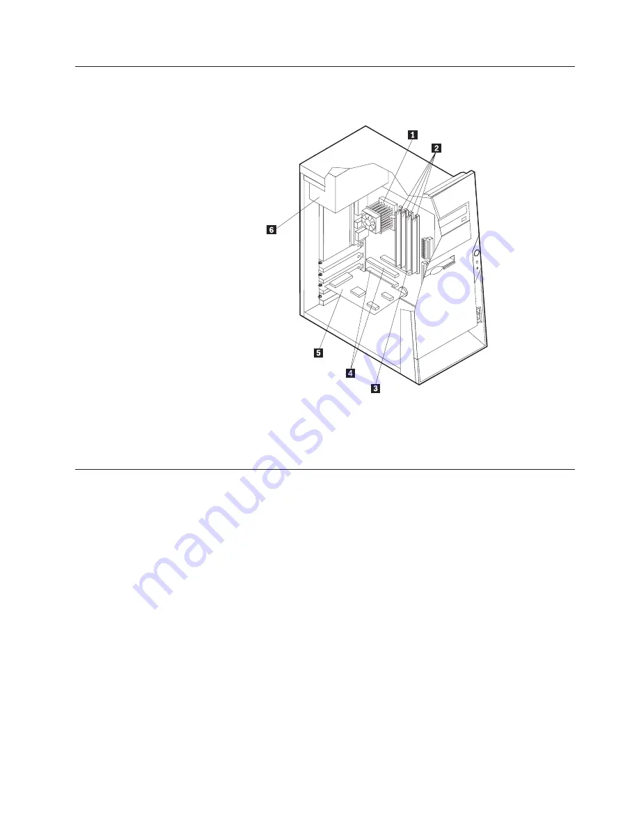
Locating


components


The


following


illustration


will


help


you


locate


the


various


components


in


your


computer.


1

Microprocessor


and


heat


sink


4

PCI


slots


2

DIMMs


5

PCI


adapter


3

AGP


slot


(some


models)


6

Power


supply


Identifying


parts


on


the


system


board


The


system


board


(sometimes


called


the


planar


or


motherboard)


is


the


main


circuit


board


in


your


computer.


It


provides


basic


computer


functions


and


supports


a


variety


of


devices


that


are


IBM-installed


or


that


you


can


install


later.


Chapter


2.


Types


8126,


8174,


8175,


and


8176


35

Содержание 808521U

Страница 1: ...ThinkCentre User Guide Types 8084 8085 8126 8147 Types 8148 8149 8174 8175 Types 8176 8177 8178 8179...

Страница 2: ......

Страница 3: ...ThinkCentre User Guide Types 8084 8085 8126 8147 Types 8148 8149 8174 8175 Types 8176 8177 8178 8179...

Страница 4: ...nt safety information on page v and Appendix E Notices on page 95 Third Edition May 2004 Copyright International Business Machines Corporation 2004 All rights reserved US Government Users Restricted R...

Страница 5: ...Available options 29 Tools required 29 Handling static sensitive devices 29 Installing external options 30 Locating the connectors on the front of your computer 31 Locating the connectors on the rear...

Страница 6: ...ttings 79 Appendix A Updating system programs 81 System programs 81 Updating flashing BIOS from a diskette 81 Updating flashing BIOS from your operating system 81 Recovering from a POST BIOS update fa...

Страница 7: ...gged so the battery safety information applies to all computers Conditions that require immediate action Products can become damaged due to misuse or neglect Some product damage is serious enough that...

Страница 8: ...mer These parts are referred to as Customer Replaceable Units or CRUs IBM expressly identifies CRUs as such and provides documentation with instructions when it is appropriate for customers to replace...

Страница 9: ...s only into a grounded electrical outlet This is a safety feature Do not defeat this safety feature by trying to insert it into a non grounded outlet If you cannot insert the plug into the outlet cont...

Страница 10: ...d when the computer is functioning or when the battery is charging Your computer produces some heat during normal operation Extended contact with the body could cause discomfort or potentially a skin...

Страница 11: ...power cords to outlet 5 Turn device ON To disconnect 1 Turn everything OFF 2 First remove power cords from outlet 3 Remove signal cables from connectors 4 Remove all cables from devices DANGER Le cour...

Страница 12: ...ttery contains lithium and can explode if not properly used handled or disposed of Do not v Throw or immerse into water v Heat to more than 100 C 212 F v Repair or disassemble Dispose of the battery a...

Страница 13: ...n t l phone situ proximit de la fuite Laser compliance statement Some IBM Personal Computer models are equipped from the factory with a CD ROM drive or a DVD ROM drive CD ROM drives and DVD ROM drives...

Страница 14: ...t de CD ROM DVD ROM est install e tenez compte des remarques suivantes ATTENTION Pour viter tout risque d exposition au rayon laser respectez les consignes de r glage et d utilisation des commandes ai...

Страница 15: ...ption use these instructions along with the instructions that come along with the option Information resources The Quick Reference that comes with your computer provides information for installing you...

Страница 16: ...entifying your computer See Chapter 1 Types 8149 8177 and 8178 on page 1 See Chapter 2 Types 8126 8174 8175 and 8176 on page 25 See Chapter 3 Types 8084 8085 8147 8148 and 8179 on page 51 xiv User Gui...

Страница 17: ...res This section provides an overview of the computer features and preinstalled software System information The following information covers a variety of models For information for your specific model...

Страница 18: ...nal modem v Remote Administration v Automatic power on startup v System Management SM BIOS and SM software v Ability to store POST hardware test results Input output features v 25 pin Extended Capabil...

Страница 19: ...s by model type Note Not all countries or regions will have these operating systems v Microsoft Windows XP Home v Microsoft Windows XP Professional Operating systems certified or tested for compatibil...

Страница 20: ...guration 0 3 kVA Note Power consumption and heat output vary depending on the number and type of optional features installed and the power management optional features in use Heat output approximate i...

Страница 21: ...ers v Within the United States call 1 800 IBM 2YOU 1 800 426 2968 your IBM reseller or IBM marketing representative v Within Canada call 1 800 565 3344 or 1 800 IBM 4YOU v Outside the United States an...

Страница 22: ...r cover or other metal surface Installing external options This section shows the various external connectors on your computer to which you can attach external options such as external speakers a prin...

Страница 23: ...tor 9 Microphone connector 3 Parallel connector 10 USB connectors 4 Ethernet connector 11 VGA monitor connector 5 Audio line in connector 12 Serial connector 6 PCI slots 13 USB connectors 7 AGP slot s...

Страница 24: ...peakers with built in amplifiers headphones multimedia keyboards or the audio line in connector on a stereo system or other external recording device Microphone connector Used to attach a microphone t...

Страница 25: ...tapes from the drives and turn off all attached devices and the computer 2 Unplug all power cords from electrical outlets 3 Disconnect all cables attached to the computer This includes power cords inp...

Страница 26: ...connector 9 AGP slot some models 4 Optional drive bay 10 Battery 5 Hard disk drive 11 PCI slots 6 Diskette drive Identifying parts on the system board The system board sometimes called the planar or...

Страница 27: ...r has four connectors for installing dual inline memory modules DIMMs that provide up to a maximum of 4 0 GB of system memory When installing DIMMs the following rules apply v System memory is divided...

Страница 28: ...hat to do next v To work with another option go to the appropriate section v To complete the installation go to Replacing the cover and connecting the cables on page 23 Installing adapters This sectio...

Страница 29: ...otective package 4 Install the adapter into the appropriate slot on the system board 5 Install the adapter slot cover latch What to do next v To work with another option go to the appropriate section...

Страница 30: ...vable media drives Note These different drives are also referred to as integrated drive electronics IDE drives Internal drives are installed in bays In this book the bays are referred to as bay 1 bay...

Страница 31: ...mm 1 0 in 3 5 inch hard disk drive preinstalled 4 Bay 4 Maximum height 25 8 mm 1 0 in 3 5 inch diskette drive preinstalled Notes 1 Drives that are greater than 43 0 mm 1 7 in high cannot be installed...

Страница 32: ...the drive that you are installing is set correctly as either a master or a slave device Note A serial ATA hard disk drive does not need to be set as either a master or a slave device v If it is the fi...

Страница 33: ...e power cable v A serial ATA hard disk drive requires a five wire power cable The steps to connect a drive are different depending on the type of drive you are connecting Use one of the following proc...

Страница 34: ...new drive 2 Locate an available SATA connector on the system board See Identifying parts on the system board on page 10 3 Connect one end of the signal cable to the drive and the other to an availabl...

Страница 35: ...manent fixture For computers designed to accommodate the rope clip knockouts at the rear of the chassis are provided To install a rope clip 1 Remove the cover See Removing the cover on page 9 2 Use a...

Страница 36: ...ough the rope clip and around an object that is not a part of or permanently secured to the building structure or foundation and from which it cannot be removed then fasten the cable ends together wit...

Страница 37: ...u are prompted to type the password to unlock the keyboard for normal use What to do next v To work with another option go to the appropriate section v To complete the installation go to Replacing the...

Страница 38: ...me after battery replacement an error message might be displayed This is normal after replacing the battery 9 Turn on the computer and all attached devices 10 Use the IBM Setup Utility program to set...

Страница 39: ...r and reconnect any cables including telephone lines and power cords Also depending on the option that is installed you might need to confirm the updated information in the IBM Setup Utility program T...

Страница 40: ...24 User Guide...

Страница 41: ...uidelines will help you work safely Features This section provides an overview of the computer features and preinstalled software System information The following information covers a variety of model...

Страница 42: ...gram this feature is called Serial Port Ring Detect for an external modem and Modem Ring Detect for an internal modem v Remote Administration v Automatic power on startup v System Management SM BIOS a...

Страница 43: ...built in features and other support programs are included Operating systems preinstalled varies by model type Note Not all countries or regions will have these operating systems v Microsoft Windows X...

Страница 44: ...al features in use Heat output approximate in British thermal units Btu per hour Minimum configuration 257 Btu hr 75 watts Maximum configuration 785 Btu hr 230 watts Airflow Approximately 0 68 cubic m...

Страница 45: ...the United States call 1 800 IBM 2YOU 1 800 426 2968 your IBM reseller or IBM marketing representative v Within Canada call 1 800 565 3344 or 1 800 IBM 4YOU v Outside the United States and Canada con...

Страница 46: ...smooth level surface and place the option on it v Do not place the option on the computer cover or other metal surface Installing external options This section shows the various external connectors o...

Страница 47: ...connectors on the front of your computer The following illustration shows the locations of the USB connectors on the front of the computer 1 USB connector 2 USB connector Chapter 2 Types 8126 8174 817...

Страница 48: ...ector 9 Ethernet connector 3 Keyboard connector 10 Microphone connector 4 USB connectors 11 Audio line out connector 5 Serial connector 12 Audio line in connector 6 Parallel connector 13 AGP slot some...

Страница 49: ...limits use a Category 5 Ethernet cable Microphone connector Used to attach a microphone to your computer when you want to record voice or other sounds on the hard disk if you use speech recognition so...

Страница 50: ...edia diskettes CDs or tapes from the drives and turn off all attached devices and the computer 2 Unplug all power cords from electrical outlets 3 Disconnect all cables attached to the computer This in...

Страница 51: ...5 PCI adapter 3 AGP slot some models 6 Power supply Identifying parts on the system board The system board sometimes called the planar or motherboard is the main circuit board in your computer It prov...

Страница 52: ...Your computer has four connectors for installing dual inline memory modules DIMMs that provide up to a maximum of 4 0 GB of system memory When installing DIMMs the following rules apply v System memor...

Страница 53: ...page 35 4 Open the retaining clips 5 Make sure the notches in the DIMM align with the tabs on the connector Push or insert the DIMM straight down into the connector until the retaining clips close Wha...

Страница 54: ...nstall an adapter up to 228 mm 9 inches long in the AGP slot PCI slot 2 or PCI slot 3 You can install an adapter up to 200 mm 7 9 inches long in PCI slot 1 To install an adapter 1 Remove the cover See...

Страница 55: ...mputer to read other types of media Some of the different drives that are available for your computer are v Parallel Advanced Technology Attachment PATA hard disk drives v Serial ATA hard disk drives...

Страница 56: ...n each bay and their height requirements 1 Bay 1 Maximum height 43 0 mm 1 7 in CD drive or DVD drive preinstalled in some models 5 25 inch hard disk drive 2 Bay 2 Maximum height 43 0 mm 1 7 in 5 25 in...

Страница 57: ...t blade screwdriver into one of the slots and gently prying it loose 5 Make sure the drive that you are installing is set correctly as either a master or a slave device Note A serial ATA hard disk dri...

Страница 58: ...ve you are connecting Use one of the following procedures for your drive connection Connecting the first CD drive or DVD drive 1 Locate the three connector signal cable that comes with your computer o...

Страница 59: ...ts on the system board on page 35 3 Connect one end of the signal cable to the drive and the other to an available SATA connector on the system board 4 Your computer has extra power connectors for add...

Страница 60: ...le or other non permanent fixture For computers designed to accommodate the rope clip knockouts at the rear of the chassis are provided To install a rope clip 1 Remove the cover See Removing the cover...

Страница 61: ...lip and around an object that is not a part of or permanently secured to the building structure or foundation and from which it cannot be removed then fasten the cable ends together with a lock Chapte...

Страница 62: ...p Utility program to set a password When you turn on your computer you are prompted to type the password to unlock the keyboard for normal use What to do next v To work with another option go to the a...

Страница 63: ...s on page 38 for instructions for replacing adapters 8 Replace the cover and plug in the power cord See Replacing the cover and connecting the cables on page 48 Note When the computer is turned on for...

Страница 64: ...es Replacing the cover and connecting the cables After working with options you need to install any removed parts replace the cover and reconnect any cables including telephone lines and power cords A...

Страница 65: ...5 To update the configuration see Chapter 4 Using the IBM Setup Utility program on page 77 Chapter 2 Types 8126 8174 8175 and 8176 49...

Страница 66: ...50 User Guide...

Страница 67: ...These precautions and guidelines will help you work safely Features This section provides an overview of the computer features and preinstalled software System information The following information co...

Страница 68: ...ake on LAN v Wake on Ring in the IBM Setup Utility program this feature is called Serial Port Ring Detect for an external modem and Modem Ring Detect for an internal modem v Remote Administration v Au...

Страница 69: ...ice drivers to support built in features and other support programs are included Operating systems preinstalled varies by model type Note Not all countries or regions will have these operating systems...

Страница 70: ...ration 0 3 kVA Note Power consumption and heat output vary depending on the number and type of optional features installed and the power management optional features in use Heat output approximate in...

Страница 71: ...You can also obtain information by calling the following telephone numbers v Within the United States call 1 800 IBM 2YOU 1 800 426 2968 your IBM reseller or IBM marketing representative v Within Can...

Страница 72: ...e the static protective package that the option came in on a smooth level surface and place the option on it v Do not place the option on the computer cover or other metal surface Installing external...

Страница 73: ...n shows the locations of the connectors on the front of the computer Note Not all computer models will have the following connectors 1 IEEE 1394 connector 4 USB connector 2 Microphone connector 5 USB...

Страница 74: ...ector 9 Ethernet connector 3 Keyboard connector 10 Microphone connector 4 USB connectors 11 Audio line out connector 5 Serial connector 12 Audio line in connector 6 Parallel connector 13 AGP slot some...

Страница 75: ...mits use a Category 5 Ethernet cable Microphone connector Used to attach a microphone to your computer when you want to record voice or other sounds on the hard disk if you use speech recognition soft...

Страница 76: ...remove any media diskettes CDs or tapes from the drives and turn off all attached devices and the computer 2 Unplug all power cords from electrical outlets 3 Disconnect all cables attached to the comp...

Страница 77: ...IMMs 5 Power supply 3 AGP slot some models Identifying parts on the system board The system board sometimes called the planar or motherboard is the main circuit board in your computer It provides basi...

Страница 78: ...Your computer has four connectors for installing dual inline memory modules DIMMs that provide up to a maximum of 4 0 GB of system memory When installing DIMMs the following rules apply v System memor...

Страница 79: ...were removed v To work with another option go to the appropriate section v To complete the installation go to Replacing the cover and connecting the cables on page 74 Installing adapters This section...

Страница 80: ...ts static protective package 4 Install the adapter into the appropriate slot on the system board 5 Install the adapter slot cover latch What to do next v To work with another option go to the appropri...

Страница 81: ...These different drives are also referred to as integrated drive electronics IDE drives Internal drives are installed in bays In this book the bays are referred to as bay 1 bay 2 and so on When you ins...

Страница 82: ...isk drive 4 Bay 4 Maximum height 25 8 mm 1 0 in 3 5 inch diskette drive preinstalled 5 Bay 5 Maximum height 25 8 mm 1 0 in Hard disk drive preinstalled Notes 1 Drives that are greater than 43 0 mm 1 7...

Страница 83: ...ve device v If it is the first CD drive or DVD drive set it as a master device v If it is an additional CD drive or DVD drive set it as a slave device v If it is an additional parallel ATA hard disk d...

Страница 84: ...supply and a signal cable that connects to the system board v A parallel ATA hard disk drive requires a four wire power cable v A serial ATA hard disk drive requires a five wire power cable The steps...

Страница 85: ...al hard disk drive can be connected to any available SATA connector 1 Locate the signal cable that comes with the new drive 2 Locate an available SATA connector on the system board See Identifying par...

Страница 86: ...other non permanent fixture For computers designed to accommodate the rope clip knockouts at the rear of the chassis are provided To install a rope clip 1 Remove cover see Removing the cover on page 6...

Страница 87: ...p and around an object that is not a part of or permanently secured to the building structure or foundation and from which it cannot be removed then fasten the cable ends together with a lock Chapter...

Страница 88: ...tection To deter unauthorized use of your computer you can use the IBM Setup Utility program to set a password When you turn on your computer you are prompted to type the password to unlock the keyboa...

Страница 89: ...dapters that were removed to gain access to the battery See Installing adapters on page 63 for instructions for replacing adapters 8 Replace the cover and plug in the power cord See Replacing the cove...

Страница 90: ...er back to the standard pins 1 and 2 10 Replace the cover and connect the power cord See Replacing the cover and connecting the cables Replacing the cover and connecting the cables After working with...

Страница 91: ...l cables and power cords to the computer See Installing external options on page 56 5 To update the configuration see Chapter 4 Using the IBM Setup Utility program on page 77 Chapter 3 Types 8084 8085...

Страница 92: ...76 User Guide...

Страница 93: ...ght start automatically when POST detects that hardware has been removed or new hardware has been installed in your computer Viewing and changing settings The IBM Setup Utility program menu lists item...

Страница 94: ...elect Set Passwords Read the information displayed on the right side of the screen Using Security Profile by Device Security Profile by Device is used to enable or disable user access to the following...

Страница 95: ...displayed on the right side of the screen 4 Select the sequence of devices for the Primary Startup Sequence the Automatic Startup Sequence and the Error Startup Sequence 5 Select Exit from the IBM Set...

Страница 96: ...80 User Guide...

Страница 97: ...ference Instructions for using the system program updates are available in a txt file that is included with the update files For most models you can download either an update program to create a syste...

Страница 98: ...pede access to the Clear CMOS Recovery jumper 5 Move the jumper from the standard position pins 1 and 2 to pins 2 and 3 6 Replace the cover See Replacing the cover and connecting the cables in the cha...

Страница 99: ...rea 2 Check the surface you are using the mouse on If you have a very intricate picture or pattern beneath the mouse it is difficult for the digital signal processor DSP to determine changes in the mo...

Страница 100: ...lers 3 inside the ball cage This build up usually appears as a stripe running across the middle of the rollers 6 If the rollers are dirty clean them by using a cotton swab soaked in isopropyl rubbing...

Страница 101: ...quires one it is just like specifying a parameter of 0 Example ATH ENTER Basic AT commands In the following listings all default settings are printed in bold text Command Function A Manually answer in...

Страница 102: ...urn to Data Mode O1 Return to Data Mode and initiate an equalizer retrain P Set Pulse dial as default Q_ Q0 Modem sends responses Sr Read and display value in register r Sr n Set register r to value n...

Страница 103: ...ow control M_ M0 Asynchronous operation P_ P0 US setting for off hook to on hook ratio P1 UK and Hong Kong off hook to on hook ratio P2 Same as P0 setting but at 20 pulses per minute P3 Same as P1 set...

Страница 104: ...Parameter b specifies automode operations where 0 automode disabled 1 automode enabled with V 8 V 32 Annex A Parameter c specifies the minimum connection data rate 300 56000 Parameter d specifies the...

Страница 105: ...Set the polled station identification FCIG Report the polled station identification FCR Capability to receive FCR Capability to receive FCSI Report the called station ID FDCC DCE capabilities paramete...

Страница 106: ...facturer REV Identify Revision Level TL Audio output transmit level VBQ Query Buffer Size VBS Bits per sample ADPCM or PCM VBT Beep Tone Timer VCI Identify Compression Method VLS Voice line select VRA...

Страница 107: ...not have Taxsignal switched OFF modem function may be impaired The impairment may be resolved by a filter with the following specifications Telekom PTT SCR BE Taximpulssperrfilter 12kHz PTT Art 444 1...

Страница 108: ...92 User Guide...

Страница 109: ...drives and diskette drives All keyboards All keylocks All memory All mice All option and adapter cards Battery 3 0V CMOS battery Control panel assembly EMC shield 5 25 Fan assembly 80 mm fixed speed F...

Страница 110: ...94 User Guide...

Страница 111: ...in certain transactions therefore this statement may not apply to you This information could include technical inaccuracies or typographical errors Changes are periodically made to the information he...

Страница 112: ...ded for home and other limited viewing uses only unless otherwise authorized by Macrovision Corporation Reverse engineering or disassembly is prohibited Trademarks The following terms are trademarks o...

Страница 113: ...RU list 93 D device drivers 8 33 59 DIMMs installing 11 36 62 drives bays 2 14 26 40 52 65 CD 5 29 39 55 diskette 5 29 55 DVD 5 29 39 55 hard disk 5 29 55 installing 15 41 66 internal 1 14 26 29 39 52...

Страница 114: ...53 R recovering from a POST BIOS update failure 82 removing the cover Types 8084 8085 8147 8148 and 8179 60 Types 8126 8174 8175 and 8176 34 Types 8149 8177 and 8178 9 replacing the cover Types 8084 8...

Страница 115: ......

Страница 116: ...Part Number 19R0764 Printed in USA 1P P N 19R0764...

Отзывы: