background image

Содержание 3720

Страница 1: ...I ...

Страница 2: ...lication Number GA33 0086 2 IBM 3720 Models 1 2 11 and 12 IBM 3721 Models 1 and 2 Communication Controllers Problem Determination System 370 30xx 4300 and 9370 Processors File Number S370 30xx 4300 9370 09 ...

Страница 3: ...l is subject to change from time to time Any such changes will be reported in subsequent revisions or Technical Newsletters Publications are not stocked at the addresses given below Requests for IBM publications should made to your IBM representative or to the IBM branch office serving your locality A form for reader s comments is provided at the back of this publication If the form has been remov...

Страница 4: ...20 problems This manual contains Problem Determination procedures Alarms hexadecimal codes Some 3720 functions you may need to identify 3720 problems A 3720 bibliography An index that contains also entries from The 3720 3721 Communication Controller Operator s Guide The 3720 3721 Communication Controller Extended Services manual Preface 111 ...

Страница 5: ...iv 3720 3721 Communication Controller Problem Determination Guide ...

Страница 6: ...te Operator Console 2 5 Permanent Ringing 2 7 No IBM Copyright Screen on Remote Operator Console 2 8 No Answer After Correct Password or 2 9 No Answer During Console Session 2 9 3720 Model 1 or 11 Load Problems If IPL Performed from Host 3 1 3720 Model 2 or 12 Load Problems If IPL Performed from Host 3 3 3720 Modell 11 2 or 12 Load Problems If IPL Performed from Disk 3 S Line Problems 4 1 CCITT V ...

Страница 7: ...exadecimal Codes Displayed on the Control Panel 7 1 Tailgate Wrap Test 8 1 Tailgate Wrap Test Messages 8 7 Console Link Test 9 1 Appendix A Task Oriented Bibliography A I Tasks to Be Performed Before Installation A I Tasks to Be Performed During Installation A 3 Tasks to Be Performed At Integration into the Network A 4 Tasks to Be Performed During Operation A 5 Abbreviations and Glossary A 7 Index...

Страница 8: ...odel 2 or 12 Modell or 11 3720 Drops Power Model 2 or 12 IConsole Problems Local Remote 3720 Modell or 11 Unsuccessful Load From Host 3720 Model 2 or 12 GO TO PAGE 1 6 1 1 5 7 1 7 1 1 1 1 11 1 5 1 13 1 7 1 15 2 1 2 5 3 1 3 3 Unsuccessful Load from Disk 3 5 Line Problems 4 1 Token Ring Interconnection Problems 4 15 Disk Problems 5 5 Power Check Lamp is On 5 1 MOSS Inoperative Lamp is On 5 3 Informa...

Страница 9: ......

Страница 10: ... panel Check the customer circuit breakers Check if there is power at the outlet If it is on Power Off set it to Power On If powered off normal condition 3720 will be powered on as soon as at least one host is powered on If on Go to page 5 1 If necessary restore power Set Power Control to LOCAL Press Power switch to power Off then On Set back Power Control to HOST If none of the above applies Go t...

Страница 11: ...anel LOCAL NETWORK WITH AUTO POWER ON Check the customer circuit breakers If necessary restore power Then Press Power switch to power Off then On Check if there is power at the outlet If none of the above applies W Go to page viii 1 2 3720 3721 Communication Controller Problem Determination Guide ...

Страница 12: ...s Power switch to power Off then On Check if there is power at the outlet If none of the above applies Go to page Ylii In case of an emergency only Power on the 3720 as follows Set the Power Control switch to Local Press Power Orf Wait 10 seconds Press Power On If the problem persits Go to page Yiii Unable to Power On the 3720 Model I or 11 1 3 ...

Страница 13: ...1 4 3720 3721 Communication Controller Problem Determination Guide ...

Страница 14: ...connected hosts is powered on If it is normal condition 3720 will be powered off as soon as all hosts are powered off If none of the above applies Go to page viii In case of an emergency only power off the 3720 by setting the Power switch to Power Off The hexadecimal code 130 is then displayed If you still cannot power off trip the customer circuit breakers Go to page viii In case of an emergency ...

Страница 15: ...H AUTO be powered off as soon as the Y PaVER ON RPO command is received RPO sent W Go to page viii In case of an emergency only power off the 3720 by setting the Power switch to Power Off The hexadecimal code 130 is then displayed If you still cannot power off trip the customer circuit breakers 1 6 3720 3721 Communication Controller Problem Determination Guide ...

Страница 16: ...decimal I I I I The retry capability is code on the control 3 0 0 attempting to power on panel If the code remains more than one minute Go to page viii Any other code Go to page 7 1 Check the Power Check lamp If on Go to page 5 1 on the control panel Check the customer If necessary restore power circuit breakers Press Power Off Check if there is Wait 10 seconds power at the outlet Press Power On I...

Страница 17: ...ITH AUTO circuit breakers POWER ON restore power Then Check if there is Press Power switch power at the outlet to power OfT then On If none of the above applies set the Power switch to Power OfT wait 10 seconds then set it to Power On If the 3720 does not power on I Go to page viii I 1 8 3720 3721 Communication Controller Problem Determination Guide ...

Страница 18: ...emptmg to power on panel If the code remains more than one minute Go to page viii Any other code Go to page 7 1 Check the Power Check lamp on the control panel If on Go to page 5 1 Check the customer circuit breakers Check if there is power at the outlet If none of the above applies If necessary restore power Then Press Power switch to power Off then On Go to page viii In case of an emergency only...

Страница 19: ...1 10 3720 3721 Communication Controller Problem Determination Guide ...

Страница 20: ...on the 3720 as follows 2 Press Power Off Wait 10 seconds Press Power On Power Check lamps If any are on Go to page 5 1 on the control panel Check the customer If necessary restore power circuit breakers Press Power Off Check if there is Wait 10 seconds power at the outlet Press Power On If none of the above applies Go to page viii Unable to Power On the 3720 Model 2 or 12 1 11 ...

Страница 21: ...1 12 3720 3721 Communication Controller Problem Determination Guide ...

Страница 22: ...Remote Power Off switch on the control panel If on Disable Set it to Enable and wait until an RPO command is sent If on Enable Check the Remote Power OfT lamp If off Normal condition The 3720 will be powered ofT as soon as the RPO command is received If on Go to page viii In case of an emergency only try to power off from the control panel Unable to Power Off the 3720 Model 2 or 12 1 13 ...

Страница 23: ...1 14 3720 3721 Communication Controller Problem Determination Guide ...

Страница 24: ...tch to DISABLE Press Power switch Off then On Set RPO switch to ENABLE if needed Power Check lamps If any are on Go to page 5 1 on the control panel Check the customer If necessary restore power circuit breakers Press Power Off Check if there is Wait 10 seconds power at the outlet Press Power On If none of the above applies Go to page viii In case of an emergency only power on the 3720 using one o...

Страница 25: ...1 16 3720 3721 Communication Controller Problem Determination Guide ...

Страница 26: ...off or from the control panel Refer MOSS is not IMLed to 3720 3721 Communication Controller Operator s Guide The IBM Copyright screen is not Go to page 2 2 r displayed after console power on No answer after correct password or No answer durin console session g Incorrect password Incomprehensible information or unexpected characters appear on the screen TERMINAL DISCONNECTED FOR REMOTE CONSOLE On a...

Страница 27: ...een modified speed etc If none of the above applies If on Go to page 5 1 If on Go to page 5 3 If on Go to page 2 3 If it is Go to page 2 3 Connect or reconnect correctly If the connection is correct perform a Console Link Test Go to page 9 1 If they have been modified reset to original values Refer to 3720 3721 Communication Controller System Integration Set the Panel Console switch to Panel unles...

Страница 28: ...tch to invite the remote console operator to power off 3 When the Remote Console Active lamp turns off power on the local console 4 If the remote console operator does not log off you can force him to log off by doing steps 5 6 and 7 5 Set to Panel o0 6 Activate Remote CNSL Disconnect Request switch to disconnect the remote console 7 Set to Console Terminal Disconnected for Remote Console or Remot...

Страница 29: ...unction Select switch to MOSS IML Activate the Function Start switch When MOSS is 1MLed COMM NOT READY 2 3161 LINE CHECK 2 3101 or SENDING IBM PC disappears and the IBM Copyright screen is displayed If not Check that the operator console parameters have not been modified Refer to the 3720 3721 Communication Controller System integration Make sure that the console cable is correctly plugged If not ...

Страница 30: ... Copyright screen No answer after correct password No answer during console session Power it on Check ifappropriate diskette Refer to the operator console documentation Power on the 3720 and IML MOSS from the control panel Refer to 3720 3721 Communication Controller Operator s Guide Console modem may be in data mode Set it to voice mode Check telephone line connections Check your telephone number ...

Страница 31: ...plies Contact the person in charge ofpasswords 1 Press PF1 2 Wait 10 seconds 3 Press PF1 again You entered an incorrect passwordfour times You entered OFF on the remote console You have been disconnected by the local console operator Operator console not in use for 30 minutes Log on the operator console Refer to the 3720 3721 Communication Controller Operator s Guide If the problem persists call t...

Страница 32: ...p is on If none of the above applies Permanent Ringing If not check the telephone line at the 3720 sid If it is try later If not power it on make it operational and in auto answer status If not plug it correctly If it is the console cannot be connected to the 3720 Ask the local operator to perform the procedure given on page 5 3 Perform a 3720 Console Link Test Go to page 9 1 Console Link Test res...

Страница 33: ...onal If none of the above applies If not power it on make it operational and in data mode If they have been modified set them to their original values Refer to 3720 3721 Communication Controller System Integration If it is perform a 3720 Console Link Test Go to page 9 1 First perform the problem determination described in the operator console documentation If the problem persists Go to page viii 2...

Страница 34: ...e lamp If off Perform problem determination of the console If on 1 Ask the local operator to IML MOSS from the control panel Activate Function Start r PF 0 o0 2 When the hex display shows FEF FE 000 or blank log on the operator console Refer to the 3720 3721 Communication Controller Operator s Guide 3 If the problem persists Go to page viii 2 When the hex display shows FEF FE7 000 or blank log on ...

Страница 35: ......

Страница 36: ... address defined for the corresponding 3720 channel adapter The NSC address is the address that you defined at installation time for the service representative If the message is UNSUCCESSFUL LOAD 1 Re initialize the 3720 Refer to the 3720 3721 Communication Controller Operator s Guide 2 At I F 1F 14 Ido NOT load the control program 3 Take a control program dump from the host 4 Go to page viii If a...

Страница 37: ...d lamps and Channel Adapter Interface switches for the concerned channel adapters If If lamp OFF Check if there is a message at switch on Bnbl the host console Go to the previous page lamp ON switch on Bnbl L 5 Go to page viii la p ON Set Panel Console switch to Panel SWItch on Dsbl Set switch to Bnbl and retry switch on Dsbl No actIOn lamp OFF Power lamp is off Power on the 3720 MOSS Inoperative ...

Страница 38: ... Inoperative lamp is on Go to 5 3 Power Check lamp is on Go to 5 1 NOTlFIFI41 Perform action required for the hexadecimal code Go to 7 1 IPL port configuration Refer to 3720 3721 Communication Controller Extended Services Host loading generation parameters Local and remote modems should be powered on and operational Modem tests are listed on page 4 13 They should be correctly plugged more on next ...

Страница 39: ...e If message is UNSUCCESSFUL LOAD 1 Re initialize the 3720 Refer to the 3720 3721 Communication Controller Operator s Guide 2 At IF iF 14 ido NOT ioad the control program 3 Take a control program dump from the host 4 W Go to page viii If none of the above Follow the Line Problems procedure on page 4 1 3 4 3720 3721 Communication Controller Problem Determination Guide ...

Страница 40: ...om disk the load could have failed for one of the following reaSORS The automatic dump load option was turned off There is no active load module on the disk A dump was required and failed because a dump already exists on the disk If ypu suspect one these reasons re Ioad the controller from the host Use the Disk IPL Information OIl function to ensure The automatic dump load option is set An active ...

Страница 41: ......

Страница 42: ...larm Go to page 6 1 If no alarm Go to step 4 CUSTOMER ID 3r IO 1 SERIAL SYSTEM INPUT N Ji IIA T TERMINATE OFF LOGOFF PF1 CUR8CIR TO IIA PF2 CQI FNCTM PF3 AL NII catFlG DATA FlUE car LnE R FlUE UF IW MIIII LW TAILE ILT CIIII JIIIIL PIDII IIDC C LItE IIIIIIF IIPLY LID NICMCCIDIE I ICI DI AIICTI_ IF LltE L1H PMIL 1 UllCT1_ HI 01 IPI INFO DII LINK 1fIL IJCP p P EWN1 LOG Dl uy I LINK taT LT PGRr FILIE ...

Страница 43: ...CCU FNC1N PF3 ALAIII ENTER A DECltIM LINE ADIIRE88 LI 42 10 IN ICNIID 3 I ccny Y24 EIA RIa3 aC 7 If CCITT V 24 CCITT V 24 CCITT V 24 V 35 CCITT V 35 CCITT V 25 CCITT X 21 LlNE TYPE PROTI ICCL non switched switched modem attachment modem attachment direct attachment modem attachment modem attachment More information on modem interface is given in 3720 3721 Communication Controller Extended Services...

Страница 44: ...t eelTT V 35 Modem Attachment 10 Ask the host operator to reactivate the line CUSTaER ID FtIICTION ON 8CREEN LltE SYSTEtt ItI UT MEA CSIA T TERMINATE CFF ITS ON NS DRS HT RI ON COON 11 SERIAL HIllER ccu FNCTN PF3 AURH CCITT V 24 CCITT V 35 4 3 ...

Страница 45: ...Wrap test results Test NOT OK Go to page viii Test OK Suspect the modem Modem tests are listed on page 4 13 Suspect the LIC cable DTR and DSR are on Make sure that the remote control unit and the modems local and remote are ready and operational Perform a Tailgate Wrap test Go to Chapter 8 1 Tailgate Wrap test results Test NOT OK Go to page viii Test OK check Modem modem tests are listed on page 4...

Страница 46: ...the status of CU8TOt R ID ttODEtt OUTIDTR ON I RTS ON NS DRS KT CCITT V 24 V 35 Direct Attachment ReV all RCV DATA STATUS PROGRESS ttODEtt 1N IDSR ON I RFS ON Rl ON COON Tl CCITT V 24jV 35 Direct Attachment 4 5 ...

Страница 47: ...rational If it is perform a Tailgate Wrap test Go to page 8 1 Tailgate Wrap test results Test NOT OK Go to page viii Test OK check LIC cable Remote control unit perform appropriate control unit tests The displayed line parameters with the network operator PF6 To display the line parameters The programmable line speed definition Refer to 3720 3721 Communication Controller Extended Services Check if...

Страница 48: ...CCITT V 25 Autocall 11 aJBTOIER 10 FUNCTICIN lIN 8CREEN LI 8Y8lEtI IIIIUT IIIEJI ellA T 115RtIlNATE IFF lOIlT aD lOIlT DATA STATUS PROGIIE88 our PVI ON fIND ON ACR ON CCITT V 2S Autocall 4 7 ...

Страница 49: ...layed line parameters with the network operator PF6 To display the line parameters Network Check if Activate command on appropriate line If it is perform a Tailgate Wrap test Go to page 8 1 Tailgate Wrap test results Test NOT OK Go to page viii Test OK PF6 Check the displayed line parameters with the network operator If correct suspect host software Check if Active command on appropriate line Chec...

Страница 50: ...CCITT X 21 Modem Attachment 11 Check the status of C and I aJII GIe ID IM FUNCTICII CII u N IIN IIPLY CCITT X 21 Modem Attachment 4 9 ...

Страница 51: ...8 l Tailgate Wrap test results Test NOT OK CZ iY Go to page viii Test OK Suspect the modem Modem tests are listed on page 4 13 Suspect the LIC cable Check if the remote control unit and the modems local and remote are ready and operational If they are not perform a Tailgate Wrap test Go to page 8 1 Tailgate Wrap test results Test NOT OK CZ iY Go to page viii Test OK check Modem Modem tests are lis...

Страница 52: ...m a Tailgate Wrap test Go to page 8 1 Tailgate Wrap test results Test NOT OK Go to page viii Test OK check Modem modem tests are listed on page 4 13 Remote control unit Perform appropriate remote control unit tests The displayed line parameters with the network operator PF8 To display the line parameters CCITT V 24 Switched Modem Attachment 4 11 ...

Страница 53: ...entation 1 Local modem self test 2 Remote modem self test 3 Modem Jine test end to end Host Channel I local I I Remote I attached I 3720 I modem modem I I 1 Self test 2 Self test 3 Modem line test 4 12 3720 3721 Communication Controller Problem Determination Guide Modem Tests Remote unit ...

Страница 54: ...nel I Local I I Remote I attached I I modem modem I 3720 I 1 Self test 2 Self test 3 Modem line test Link level 2 test from the host If test OK suspect remote control unit or host generation parameters Local Loopback test loop 3 LOCAL LOOPBACK TEST LOOP 3 Channel attached Local Remote Remote Host 3720 l odem r l Junit Remote Loopback test loop 2 REMOTE LOOPBACK TEST LOOP 2 Remote unit Modem and Li...

Страница 55: ... 4 14 3720 3721 Communication Controller Problem Determination Guide ...

Страница 56: ...rm Go to page 6 1 If no alarm Go to step 4 37 10 11 _IM SY8TEII IIIIUT MfE A eSIAt T 1EIItlNATE OFF LOGOFF 1 CURICII TO IIA PF2 CCU FNC1N fIII3 ALAIII CGI IG DATA FlU LINI Ia It FlU LIF IMCIfINl Lw T II T c awna NIIC C LINI IIIIW IIPLY UD MICIIDCGIII Fa DI FUCTt OF LINI L1H __ IGIII 01 IPL UI O DII LI IPL pans LIllI UlDDlM AY I LI LT FILl lIS 111 _ III LOMI uc _ UID 11n 11U III ICAIIIIIt II LOMI u...

Страница 57: ...INATE OFF LOGOFF PFl HOVE TO SIA PF 2 CCU FNCTN PF3 ALARM TRA TIC SELECT ENTER A DECIHAL LINE ADDRESS XX TO YY _ TRA LINE ADDRESS TIC S 02 016 017 1 2 TYPE A TO ALLOW ACTIVATE LINK COMMAND PRESS SEND TO CONFIRM 5 Enter the decimal address of the line then ISEN 6 PF6 The following screen is displayed 4 16 3720 3721 Communication Controller Problem Determination Guide ...

Страница 58: ...dicators are either ON or blank Refer to page 4 18 A message indicating an error condition of the selected TIC if one exists Refer to page 4 20 TRM activity information A display of the IR BR bits of the selected TRA and TIC ON or blank The IR bit indicates that an interrupt is pending from the selected TIC The BR bit indicates that a data transfer request DMA is pending for the TIC A change of th...

Страница 59: ...MILE STATICII RINC REO IRY m IILICT Unplug the TIC cable from the 8228 Multiple Access unit Reactivate this TIC Press PFS for REFRESH TRANSMIT BEACON IF you have an OPEN ERROR message go to FUNCTION FAILURE page 4 21 HARD ERROR only If the Ring Status display is ON for LOBE WIRE FAULT without any other status ON replug the TIC cable to the 8228 IBM Multiple Access unit and refer to page 4 23 in co...

Страница 60: ...etermination If the problem persists Reactivate the line for this TIC Press PFS If the problem persists Check the reason why the 3720 was forced ofT the ring When the problem is corrected reactivate the line to this TIC If other Stations are known to be working on the ring try another 8228 plug If the problem persists refer to page 4 23 in conjunction with the IBM Token Ring Network Problem Determ...

Страница 61: ...II COIIfIIR 0 ERFUIIf lINGLE 8TATlON C TRI ERRIIR G C _ NIiA RINC REaM RY PFS IEFNiSI PF8 IILI CT 1 BRING UP ERROR MESSAGES BRING UP ERROR X 1 to 6 Activate the link from the host If the problem persists 2 INITIALIZATION ERROR MESSAGES INITIALIZATION ERROR XX 1 to 7 INITIALIZATION ERROR XX 8 to 13 Check the installation Generation parameters When corrected reactivate the link to this TIC If the pr...

Страница 62: ...ON in the Ring Status area without any other status ON change the TRA cable 2 Otherwise use new symptom to continue the problem determination Reactivate the link to this TIC Press PFS If the problem persists refer to page 4 23 in conjunction with the IBM Token Ring Network Problem Determination Guide Reactivate the link to this TIC If the problem persists refer to page 4 23 in conjunction with the...

Страница 63: ... described for this symptom Check the installation generation address for this TIC If there is no problem refer to page 4 23 in conjunction with the IBM Token Ring Network Problem Determination Guide Reactivate the link to this TIC If the problem persists 0 Check with the Token Ring operator Correct the problem and then reactivate the link to this TIC The adapter is in the same state as after init...

Страница 64: ... removed device run the adapter diagnostic use this device to determine ring status by loading a network application program Does the Ring Diagnostic indicate or Does the observer terminal indicate Understand Refer to the NPDA Link Configuration Detail screen for the Alert corresponding to the ring beaconing condition Deactivate link for this TIC at the host Unplug the cable from the access unit T...

Страница 65: ...4 24 3720 3721 Communication Controller Problem Determination Guide ...

Страница 66: ... Power Control switch to Local Press General Reset Wait 10 seconds Press Power On switch to power Off then On If the problem persists go to step 3 3 Go to page viii 3720 Model 2 or 12 and provide that hexadecimal code IPower Check Lamp s is On Power Check lamp is on BB rLJu Go to page viii _ r rLJ u and give the name of the Power Check lamps that are on DDD DD Power Check Lamp s is On 5 1 ...

Страница 67: ... 5 2 3720 3721 Communication Controller Problem Determination Guide ...

Страница 68: ...n Start switch When MOSS is IMLed the Hex Display shows FEF FE7 000 or is blank Set the Function Select switch back to Normal If FE7 set MOSS online from the operator console Microcode Change Transfer MOSS dump to the host so that it can be printed for later use by the 3720 service representative If the problem persists Do not transfer the last MOSS dump Note the hexadecimal code Go to page viii a...

Страница 69: ...5 4 3720 3721 Communication Controller Problem Determination Guide ...

Страница 70: ...ibed under Disk Functions in 3720 3721 Extended Services Re IPL the NCP from host and save it on disk 2 If the problem persists or the disk restore fails W Go to page viii and Switch to diskette mode so that you can initialize the 3720 Switching to diskette mode is described in 3720 3721 Operator s Guide Disk Problems Disk Problems 5 5 ...

Страница 71: ...5 6 3720 3721 Communication Controller Problem Determination Guide ...

Страница 72: ...ine s or Token Ring s If message on several lines of same scanner If message on one line If message on one Token Ring Host Messages Go to Chapter 6 Identify in the message the control unit address If the control unit is a 3720 Go to page viii If the control unit is not a 3720 refer to the control unit documentation Perform a route test if available in the operating system If not available Go to pa...

Страница 73: ...5 8 3720 3721 Communi ation Controller Problem Determination Guide ...

Страница 74: ...II l ERIN tIllER I UNCTICIN CIt SCREEN tw HINE LVi TML 8YI1IIt IftIUT lEA eSIAt T TElltINA1E OFF LOGOFF WI tIDVE TO alA lin CQJ FNCTN fIF3 ALAIIt Yla AR14 VER81C1M4 EC LE 4EL 0 111_ LAST APPLIED ttCF 18C1A01l The above screen displays The version of the control program that is loaded in the CCU The control program load name The control program load identification when the control program is loaded...

Страница 75: ...5 10 3720 3721 Communication Controller Problem Determination Guide ...

Страница 76: ...RIIINATE OFF LOGOFF PFl MOVE TO 81A PF2 CQI FNCTN PF3 AURIt CP RUNNING DI canENTS LOAD tIIIII I E8 AUTO IL OAD ACTIVE LOAD IIIDULE lIN IN fIIlCIGII S8 va PF4 CHANCE AUTO 1l OAD OPTION Use the Disk IPL Information function to PFI I PUReE Display the status of control program load modules and dump as well as the automatic dump load option setting on the MOSS disk Change the automatic dump load optio...

Страница 77: ...5 12 3720 3721 Communication Controller Problem Determination Guide ...

Страница 78: ...s 6 4 NPDA V3 Messages 6 5 VTAM Alerts 6 6 How to Display an Alarm Once generated the alarm is automatically displayed and an audible signal is heard if the console is logged on CUSTotER ID 3720 1 SERIAL NUtIJER SYSTEM INPUT AREA SIA T TERMINATE OFF LOCOFF PFl HOVE TO SlA PF2 CCU FNCTN PF3 ALARH ALARM When an alarm is already displayed you are informed that another one is waiting for display by th...

Страница 79: ...clear the displayed alarm note the reference code If you forget to do so select the Event Log function to display all the alarms The Event Log function is described in 3720 3721 Extended Services 6 2 3720 3721 Communication Controller Problem Determination Guide ...

Страница 80: ...ANNER xx ERROR LINES xxx yyy RE IML SUCCESSFUL 6 21 A19 SCANNER xx ERROR LINES xxx yyy RE IML SUCCESSFUL 6 22 A20 SCANNER xx ERROR LINES xxx yyy 6 23 A21 SCANNER xx ERROR LINES xxx yyy 6 24 A22 SCANNER xx ERROR LINES xxx yyy RE IML FAILED 6 25 A23 SCANNER xx ERROR LINES xxx yyy RE IML FAILED 6 26 A24 SCANNER xx ERROR LINES xxx yyy RE IML FAILED 6 27 A25 REMOTE CONSOLE ERROR LINE MODEMS CONSOLE MOS...

Страница 81: ...LED 6 25 alarm 22 HARDWARE ERROR SCANNER RE IML FAILED 6 27 alarm 24 INITIALIZATION FAILURE RING INTERCONNECTION COUPLER 6 31 alarm 29 INITIALIZATION FAILURE RING SUBSYSTEM ATTACHMENT 6 31 alarm 29 MOSS LOCAL CONSOLE ERROR CONSOLE ADAPTER CABLE 6 12 no alarm MOSS OFFLINE MAINTENANCE MODE 6 13 alarm 6 MOSS REMOTE CONSOLE ERROR CONSOLE 6 29 alarm 26 NCP LEVEL 2 ERROR RING INTERCONNECTION COUPLER 6 3...

Страница 82: ...IC 48 1_AE l t _ BUICI ID 04E EMIIR A to VIEII ACTION DI uV II IIA If Action Go to page 01 6 8 no alarm 02 6 9 alarm 2 03 6 10 alarm 3 04 6 11 alarm 4 05 6 12 no alarm 06 6 13 alarm 6 07 6 14 alarm 7 08 6 15 alarm 8 09 6 16 alarm 9 OF 6 18 alarm 15 10 6 19 alarm 16 11 6 20 alarm 17 12 6 21 alarm 18 13 6 22 alarm 19 14 6 23 alarm 20 15 6 24 alarm 21 16 6 25 alarm 22 17 6 26 alarm 23 18 6 27 alarm 2...

Страница 83: ... 6 11 alarm 4 05 6 12 no alarm 06 6 13 alarm 6 07 6 14 alarm 7 08 6 15 alarm 8 09 6 16 alarm 9 15 6 18 alarm 15 16 6 19 alarm 16 17 6 20 alarm 17 18 6 21 alarm 18 19 6 22 alarm 19 20 6 23 alarm 20 21 6 24 alarm 21 22 6 25 alarm 22 23 6 26 alarm 23 24 6 27 alarm 24 25 6 28 alarm 25 26 6 29 alarm 26 30 6 32 alarm 30 31 6 33 alarm 31 32 6 33 alarm 31 6 6 3720 3721 Communication Controller Problem Det...

Страница 84: ...ollowing values FE8 Alternative current ac provided by the user was temporarily interrupted FEB The position of the Function Select switch is incorrect FED MOSS IML complete with non fatal errors zzz can have the value FEe Serial number not initialized Action Contact the hardware service representative page viii and provide the reference code except for yyy FE8 Check your alternative current yyy F...

Страница 85: ...ne from the operator console 8000 ISEtG Transfer MOSS dump to the host so that it can be printed for later use Refer to Advanced Communication Function for Network Control Program and System Support Diagnosis Guide If the problem persists Do not transfer the last MOSS dump Note the NCP MOSS interface status QI for VTAM or QUALIFIER 1 for NPDA and the hexadecimal code if any Note the status of the ...

Страница 86: ...ion Function for Network Control Program and System Support Diagnosis Guide MOSS has been automatically re IMLed If the problem persists Do not transfer the last MOSS dump Contact the hardware service representative page viii and provide the reference code NPDA V3 Detail Screen NETIIORK COIIIJNICATIONS COHTRQL FACILITY NCFOI 0PER1 EVENT DETAIL NCFOI P2AL4Y2 DOIIAIN I COle I DSI1S1118 lS 48 44 PAGE...

Страница 87: ...e In diskette mode do not power off and do not initialize the 3720 hhmmss Contact the hardware service representative page viii and provide the hexadecimal code displayed on the control panel NPDA V3 Detail Screen NITIIIIIC c aMlUtlCATICItII cama FACILITY IafOt t hIIIf IIITAIL DINI at at l1 1C M TICIN CII ILOCIC 10 D4I INIIII A 10 WID M TICIN OIll UY II IIA 6 10 3720 3721 Communication Controller ...

Страница 88: ...le use another diskette In diskette mode do not power off and do not initialize the 3720 Contact the hardware service representative page viii and provide the hexadecimal code displayed on the control panel NPDA V3 Detail Screen JENIRIC CGtIUtICATICNI COIfIRIIL FACILITY 10 01 CIPIRt IRM EVINI DETAIL DllllAIN I CIIttC I 1IIICIt1f T1 PIUIMLE CMME CIWIDIMIIEJIII 01 1 EVINI TtPE 01 GEIERM 01 tl BlFIC ...

Страница 89: ...adapter Action Follow problem determination procedure Local Operator Console page 2 1 NPDA V3 Detail Screen _ _ CGfIUdCATI_ CIIIIMI acIUTY IDOl Cl lltl 4IIC IlWIIT rAIL IIIIIMDI I CDIIC I IIIICItrI rIGII aa GDI MoAY 1 _ U t at t ___ _i IlWIIT TWIt 01 GIIBAL 01 I IC 41 M TIGII aaac ID 041 DfIIR A TO Villi ACT lMoAT OA tONSOLE CAC REFERENCE CODE DETECTED EXCEPTION OC CONSOLE CAC DETECTED ERROR to CO...

Страница 90: ...d If no longer in maintenance mode set MOSS online hhmmss If MOSS is still not online see MSA re IML MOSS If the problem persists Contact the hardware service representatives page viii NPDA V3 Detail Screen CIIIIIIICAnCIMI CGIIIIIIL MlILt1Y IUGl GPa1 4311 IWNr IIITAIL DlNIN I CCIIC I 1IDCIt1l f1 CIMIIIIMMIIdCRlCGlll aFl LUIb l 4IIIf T fIIIE 04 GIIBM 01 urIC M TI aGCIC ID CME IIIIIIt A 10 via M TIG...

Страница 91: ...AD IN PROGRESS ON Lxxx reload the control program from the host when FF4 is displayed on the control panel Reactivate the affected line s from the host when IPL is completed Contact the hardware service representative page viii and provide the reference code if any NPDA V3 Detail Screen NIinICII C IUUCATlClNB CCH IRIlL FACILITY tCFOl ClPERI 1I IIA 4311 EVENT IETAIL tCFOl P3AL4Y2 IDIAIN I IDIC I II...

Страница 92: ...SS ON CAxx or LOAD IN PROGRESS ON Lxxx Reload the control program from the host Reactivate the affected line s from the host when the IPL is completed If the problem persists 1 Dump the control program using NCP facilities or DYNADUMP facilities described in your control program documentation 2 Analyze the dump If you did not solve the problem Contact the software service representative page viii ...

Страница 93: ...ut 9 lI n 1 __ L t V H J VU I i H J U5U1j If you did not solve the problem Contact the hardware service representative page viii and provide the reference code NPDA V3 Detail Screen fETIIIIRI COI lInCATIONS COImIIII FACILITY NCI 01 1 NPIM 4311 EVI H1 DETAIL r CISI1S188 15 48 44 PAGE 1 IF 1 OUALIFIERS U t t 2 t t EV NT TYPE 01 f SPECIFi i l IOII oa ILOCIC ID ME ENTER A 10 VIEW AC1 ION IlI t Ay NPIM...

Страница 94: ...Refer to 3720 3721 Communication Controller Extended Services manual Action Retry You may retry from the 3720 operator console If the problem persists Perform the action required for the hexadecimal code displayed on the control panel page 7 1 If you did not solve the problem Contact the bardware service representative page viii and provide the reference code Alarms 6 17 ...

Страница 95: ... hardware service representative page viii and provide the reference code The BY2 reference code contains the following information BY2xxyzz where xx line threshold y I to 4 LIC type 1 to 4A 5 LIC type 4B zz line address 00 to 63 NPDA V3 Detail Screen NE nIIRC CCIIIUIICATICIIII CGN1 IIIL ACILITY NCFOI CI IiR1 I M IEVEIn EAIL IlllllAIN I COlIC I CISIISIII IS 48 44 PAGE I CF I IIEICIIlPTICIN CIWllll...

Страница 96: ...DWARE MICROCODE SCANNER VTAM 721 UAC 16 Ql Q2 Cause Scanner error Action No action required Wait until the completion of the automatic scanner re IML NPDA V3 Detail Screen CllllllGCATa FacILIty _ _AlL U _ _ 1 r J 1WI a 01 IP1C II acnae 10 ID __ A 1U VIIIf acnae It II IIA SCANNER LOVER AIG lFPER POSITION LINE AIIJRESS RANCE hhm Alarms 6 19 ...

Страница 97: ...ML NPDA V3 Detail Screen NEMlRK COIIIUNJCATlC1N8 CON I ROI FACILITY IICFOt IllERI 1FOA 4311 EVENT IETAJL NCFDI PaAL4Y2 DllllAJN I CCIIC I DESCRIPTJON PR08AILE CAUBE C8ClFTVAAE Jat COIIIUN CTRL PRetlI QUALIFIERS U L _ _ _ _ _ _ 2 l _ _ _ _ _ _ 0ISI1S188 15 48 44 PAGE I CIF 1 EVENT TYPE 04 GENERAL 02 ReJFIC 30 ACTJON 11 ILOCIC m 04E EHlER A TO VIEW ACTJON IIII LAY IFOA SCANNER POSITION LOWER AND UPP...

Страница 98: ...r Action Reactivate affected line s from the host and retry If the problem persists Contact the hardware service representative page viii and provide the reference code NPDA V3 Detail Screen _III I CIIIC I IIUClU ICIII I ICMIB IIMLIFI U 1 _______ a 1 _______ I 1 _______ EWiNf TWt CD GI8M 01 a lF1C U ACTlCIII 1a aCI ID _ A 10 YID M TICIII III LAY SCANNER LOVER AJiI UPPER REFERENCE POSITION LItE ADD...

Страница 99: ... the control program using NCP facilities or DYNADUMP facilities described in your control program documentation Analyze the dump If you did not solve the problem Do not transfer the last scanner dump Contact the software service representative page viii and provide the reference code NPDA V3 Detail Screen NENIRIC CGIIUIICATlIINB CONlIII FACILITY NCFOI OPERI EVENT DETAIL DllllAlN I COlIC I IlElCRI...

Страница 100: ...ge viii and provide the reference code NPDA V3 Detail Screen CGIIIINICATICIB c ama FACJLJlY ICF01 CftRl II DA EVENT IETAR NCFOI P W 4 12 IN I COlIC I IB ItII 1 JCIN 1aa aDE ICMIDI CI5I1S181 15 48 44 PMESCFl IUM lFIERI 1 ___ ___ __ J aI __________ __ J 31 L _ _ __ _ _ DIM1 TYPE 01 GIiI8W 01 II ECIFJC 11 ACTJCIN 14 IIUICIC m 04E III1IIt A TO VIEW M TICIN Ill UY II DA SCAHIER LOWER AND UPPER REFERENC...

Страница 101: ... Analyze the dump If the problem persists Contact the software service representative page viii and provide the reference code NPDA V3 Detail Screen NE1 IIIIIIC CCIIIUdCATlCINI catmIIIL FACILITY 10 01 OPERI 1IPDA 43t EVENT IETAIL OOItAIN I COlIC I 1lElCR11 T1Cli PIIII8MI CMIII C8III 1VARE I CCIIIUf CTRL PRGIII CISIIS1811 IS 48 44 PAGE I CF I r r 1llAL1F1IR8 II 1 _______ 21 1 _______ 31 1 _______ E...

Страница 102: ...vice representative page viii and provide the reference code NPDA V3 Detail Screen IIE nIIIRk aJIIUdCATIC18 CGIII1IIL fM IUTY 10 01 CI IRI II IIA EWIIT AlL DaMlli I CGIC I IIIICRlPfllll JIRIIIAILE CMa CIWIIIIAIEIIIlCROCGDE _ I r r l1III II 1 _______ al 1 _______ II 1 _______ EVBn TYPE 01 CIENEIW 01 81 1 1ClflC at M Tl1II 11 10 CME IIff IIl A TO YDV ACTIIli lRAY II IIA SCANNER LOVER ANJ lPPER REFER...

Страница 103: ...ion Analyze the dump If the problem persists Contact the software service representative page viii and provide the reference code NPDA V3 Detail Screen NE NRC COIIIlNICATI CONlRIIL FACILITY NCF111 ClPERI 05I1S188 1S 48 E EM1 DErAIL PAGE 1 IF 1 DOMIN I COtIC I ClElCRIPTIIli PRIIUI8L CAllIE ICFlVARE I CIIIIIUN ClII PRGIII r IILW JFIERI 11 I I 2J I I 3 I I MIlT TYPE 01 f n 1ACr 1II 17 frO 04I EMT EII...

Страница 104: ...rvice representative page viii and provide the reference code NPDA V3 Detail Screen IIE11IDIIC CGllllNlCATl CIIImIIIL FAClUTf IICI Ot Cl Bt II IIA PIICI IETAlL IlllllAlN I CIIIC I I8 RlI 1 lCli PNaMLE ClUE ctWIJIIAMIIIlCllllCOlll ICNNItI r IlMUFIIIIS 11 1 _______ 2 1 _______ 31 1 _______ lWIIT M E 01 _ _ 01 lFlC 11 ACTlCIII 18 IUICIC m 04E IIITIIt A 10 YIn ACTlCII llPLAY II IIA SCAtIER LOVER AN UP...

Страница 105: ...emote console adapter Action Follow the Remote Operator Console procedure page 2 5 NPDA V3 Detail Screen _ CGIIUfICATIONI CGN1RIIL FACILITY NCFIIl CII ER1 1IPQj 4311 IM NI IlETAtL 1 I COlIC I CllV1S188 lS 48 44 PAGE 1 1 IIIICItIPTICIN fIIUIIMI IIWIIIIMKIIUCIIIICGDE ICE llGMlDlDI yl IF _ 11 r j EVENT TYPE 01 ailaL l ii 8I ECIFIC 48 M TICIN 18 lUCK 10 D4E IIITD A RI WID M TICIN I y IIPQj REFERENCE C...

Страница 106: ...se MOSS remote console Action Follow the Remote Operator Console procedure page 2 5 NPDA V3 Detail Screen CllllUdCATI c GNI FACILllY ICfOt CI at li ii0 _ IWIIf IIITAIL IICIMIN I CIIIC I 1 l1li l awICIIIII aYIIMIDIDIM AY UUFIIII8 U C J hhmmss reference code I IIIT 01 QIIIIIUI 01 cIFIC M TICII lA ILDI IC m a IN1 IR A TO YUV M TIIII M AY li iio REFERENCE CODE Alarms 6 29 ...

Страница 107: ...G MULTIPLEXER Cause Token Ring Multiplexer TRM Error Control Program Error Actio Reactivate affected token ring adapter s frem the host hhmmss reference code If the error occurs repeatedly contact the appropriate service representative page viii and provide the reference code if any 6 30 3720 3721 Communication Controller Problem Determination Guide ...

Страница 108: ...Ring Interconnection Coupler TIC Error Token Ring Multiplexer TRM Control Program Error Action Transfer the TIC dump file to the host so it can be printed for later use by service representative The dump transfer and print are documented in Advanced Communication Function or Network Control Program and System Support Diagnostic Guide SC30 3181 Reactivate affected token ring adapter from the host I...

Страница 109: ...ode as follows I Install the primary diskette on which you saved the disk 2 Set the Function Select switch to Diskette Mode 3 Activate the Function Start switch For more information refer to the 3720 3721 Communication Controller Operator s Guide Switching to Diskette Mode r NPDA V3 Detail Screen IE MIII CClllUllCATlC1N8 CGN1 AIL FACILITY NCI OI Cll ERI 1I OA 43 I IWNI IETAIL ClDMAIH I COMe I 0lIl...

Страница 110: ... error Communication controller error Action The 3720 has been re initialized An NCP dump has been saved on the 3720 disk use the VTAM MODIFY command to 1 Transfer the dump then 2 Purge it from the 3720 disk once the dump has been transferred The current dump may not be transferred but it has to be purged Otherwise the next dump will not be taken on the 3720 disk and will be lost Reactivate the af...

Страница 111: ...dump 2 Purge it from the 3720 disk once the dump has been transferred The current dump may not be transferred but if it is not purged the 3720 automatic IPLjDUMP is deactivated Retry 3720 initialization Reactivate the affected line s from the host If the problem persists do not purge the dump but transfer it and contact your software service representative page viii and provide the reference code ...

Страница 112: ...r error Action The 3720 initialization has failed The control program has not been dumped on the 3720 disk because of a disk error A30 Retry 3720 initialization Reactivate affected lines from the host If the problem persists contact the appropriate service representative page viii and provide the reference code if any Alarms 6 35 ...

Страница 113: ...6 36 3720 3721 Communication Controller Problem Determination Guide ...

Страница 114: ...lization indicate error or status condition I I 10 RATId 10 VER I 10 I D POVERON POVER OFF lo D POIIERON PDVER OFF FUNCTION SELECT GENERAL FUNCTION RESET REIlUEST START DOD CHAIlEL ADAPTER INTERFACE PANEL IA 19 IA 28 POIIER CONTROL OO ODD CONSIJ E 3720 Model 1 or 11 Control Panel HIlST WITH AUTO POVER ON LOCAL NETVORK VITH AUTO POVER ON FUNCTION SELECT GENERAL FlN TION 0 EjiJ 0 RE OTE POVER PANEL ...

Страница 115: ...ctly Contact the hardware service representative page viii You powered off the 3720 Model 1 from the control panel although the Power Control switch was positioned on Host with Auto Power On or on Network with Auto Power On Contact the hardware service representative page viii Autorestart in progress If this code remains more than one minute Contact the hardware service representative page viii St...

Страница 116: ... page 9 8 Plug correctly the wrap block at the end of the local modem cable of the remote console Go to Console Link Test on page 9 8 Plug correctly the wrap block at the end of the local modem cable of the RSF connection Go to Console Link Test on page 9 8 There is a problem at the local console attachment Go to Console Link Test on page 9 5 There is a problem at the local modem attachment for th...

Страница 117: ... checking in progress Mount the secondary diskette Secondary diskette checking in progress Mount the primary diskette Microcode change from primary diskette in progress Mount secondary diskette Microcode change from secondary diskette in progress Contact the hardware service representative page viii 7 4 3720 3721 Communication Controller Problem Determination Guide ...

Страница 118: ...mary and secondary diskettes are not at the same microcode level EC level Contact the hardware service representative page viii The microcode change failed because you activated the Function Start switch Activate the General Reset switch The procedure will start Mounted diskette is not a primary one Mount a primary diskette The procedure continues Mounted diskette is not a secondary one Mount a se...

Страница 119: ...ge failed Retry from step 1 with the backup diskettes If it fails Contact the hardware service representative page viii File not found on disk Contact the hardware service representative page viii File not found on disk Contact the hardware service representative page viii File smaller on diskette Contact the hardware service representative page viii Disk directory capacity is exceeded Contact the...

Страница 120: ...e service representative page viii Contact the hardware service representative page viii Mounted diskette is not an expansion diskette MCF apply error at installation time Contact the hardware service representative page viii Contact the hardware service representative page viii 3720 3721 set up instructions starting See EE6 The primary diskette is being copied onto the disk The primary diskette i...

Страница 121: ... not be written onto the disk Restart the Setup Test Contact the hardware service representative page viii Mount the expansion diskette Contact the hardware service representative page viii 3720 3721 set up instructions successfully completed Contact the hardware service representative page viii MOSS IML step 1 If permanent contact the hardware service representative page viii 7 8 3720 3721 Commun...

Страница 122: ...e mode 3 Activate the Function Start switch In diskette mode you cannot perform 3720 functions Contact the hardware service representative page viii Contact the hardware service representative page viii Switch to diskette mode to initialize the 3720 The procedure is given under the description of the hexadecimal code F14 Contact the hardware service representative page viii Control program initial...

Страница 123: ...IPL Port function The control program is not compatible with the MOSS level Error in the control program initialization Take a 3720 main storage dump from the host then Check the system generation parameters options related to the control program information table CPIT Buffer length prefix length Ll L2 L3 L4 CRP buffer lengths control program type Contact the hardware service representative page v...

Страница 124: ... error Alternative current ac provided by the user was temporarily interrupted Contact the hardware service representative page viii MOSS IML is completed with errors MOSS IML is offline MOSS IML is completed The control program is loaded MOSS IML is completed The control program is not loaded MOSS is alone Start of 3720 initialization IPL Initialization of the CCU phase 1 Load and start of contro...

Страница 125: ...ogram initialization begins If temporary No action required If permanent Contact the hardware service representative page viii Contact the hardware service representative page viii Contact the hardware service representative page viii Initialization IPL is completed with console communication adapter errors Contact the hardware service representative page viii Contact the hardware service represen...

Страница 126: ... For a LIC 3 Male wrap cable P N 6398696 Power on and log on the operator console Logon procedures are documented in 3720 3721 Communication Controller Operator s Guide S To position the cursor 2 0 2 I SEtCl To select the Wrap Test function CUSTCIER ID 3720 1 SERIAL NJIEER FUNCTION ON SCREEN WRAP TEST IYSTEIt INPUT MEA SIA T TElIUNATE OFF I OCOFF W1 MOVE TO IIA PF2 ccu FNCTN PF3 ALARtt WRAP TEST I...

Страница 127: ... SYSTEM INPUT AREA SIAl T TERHINATE OFF LOCOFF PFl ItOVE TO SIA PF2 ccu FNCTN PF3 ALARtt RAP PATTERN SELECTION LItE ADDRESS 80 TYPE CONTROl LEAD L YEL TAILGATE LCD 4 STARTIST IO an CNTRL PCH NCP LIe TYPE 1 SELECT ONE lOTION Cl TO 31 1 USE EEFAU T PATTERN 2 DISPLAY EEFAlLT PATTERN 3 CREATE PERSONAL PATTERN PFS CANCEL To use the default pattern The following screen is displayed 8 2 3720 3721 Communi...

Страница 128: ...LARII WRAP TEST START LINE ADDRESS 80 TYPE CONTROL LEAD LEYQ TAILGATE LCD 4 STARTISTDP an CNTRL PCtt NCP LIC TYPE 1 ENTER NUtIIER OF VRAPS tl 2SS OR P P PERtWENT IIRAP PLUG APPROPRIATE IIRAP FACILITY AT TAILGATE THEN PRESS SEND TO START THE WRAP PFS CANCEL To perform 10 wraps Remove the corresponding LIe cable from the tailgate Tailgate Wrap Test 8 3 ...

Страница 129: ...nding position at the tailgate For LIC 1 2 4A or 4B Male wrap plug PfN 6398695 For LIC 3 Male wrap cable PIN 6398696 For LIC 1 2 4A or 46 For LIC 3 I SEN To start the test 8 4 3720 3721 Communication Controller Problem Determination Guide J ...

Страница 130: ...There is no incorrect pattern All transmitted wraps have been received correctly In this case terminate the function 80 ISENl and return to the problem determination procedure for specific action or The test is NOT OK There is an incorrect pattern Go to page viii A screen similar to the following one is displayed Additional information can also be displayed about the scanner For more information r...

Страница 131: ... TO DISPLAY FIRST INCORRECT PATTERN l To display the incorrect pattern A screen similar to the following one is displayed j L _ _ _ _ _ _ _ _ _J CUSTOtER ID 3720 1 SERIAL NUIIIER FUNCTION ON SCREEN RAP TEST SYSTEM III UT AREA SIAl _ T TERHINATE OFF LOCOFF PFl IIIYE TO SIA PF2 COl FNCTN PF3 ALARH LIrE ADDRESS 80 CONTROL LEAD RAP INCORRECT PATTERN TRAtatITTED PATTERN 11111011 10000011 EXPECTED PATTE...

Страница 132: ...se A physical error occurred when communicating with the eeu The Wrap Test function is canceled Action Check that the eeu is correctly IPLed and that MOSS is online MSA field c should display MOSS ONLINE Select the Wrap Test function another time If the problem persists contact the hardware service representative page viii CDF NOT CREATED WRAP FUNCTION CANCELED Cause The 3720 configuration data fi...

Страница 133: ...ause The digits that you entered are either less than eight or not binary Action All dots of the field in error must be replaced by zeroes or ones INVALID INPUT Cause You did one of the following You pressed SEND before entering the requested input on a screen You entered one or more invalid characters You entered an invalid value for example an address outside the specified range or You made a fo...

Страница 134: ...ress and the wrap type and level make sure that the line is disabled or deactivated before pressing SEND LINE NOT SYSTEM GENERATED WRAP FUNCTION CANCELED Cause The line that you specified had not been defined at CCU control program generation time The Wrap Test function is canceled Action Select the Wrap Test function another time and specify a valid line address LINE TEMPORARILY NOT AVAILABLE WRA...

Страница 135: ...nline MOSS ONLINE is displayed in MSA field c If the control program supports the wrap tests select the Wrap Test function another time and try again If the problem persists contact the hardware service representative page viii NO SUPPORT FOR ALC LINE WRAP FUNCTION CANCELED Cause The wrap tests functions cannot be performed on ALC lines The Wrap Test function is canceled Action None NO SUPPORT FOR...

Страница 136: ...NABLE TO SET LINE TO WRAP MODE WRAP FUNCTION CANCELED Cause The wrap tests cannot be performed on the line that you specified for any of the following reasons Modem is not powered on Modem is not set on the appropriate test position There is a hardware error in the modem cable or scanner The error code is given in the Line Communication Status byte LCS on the Wrap Test Result screen A BER is creat...

Страница 137: ...t function by pressing PF5 A tion None WRAP TEST COMPLETED Cause The wrap has been performed the number of times that you specified The test is now completed Action If there is an incorrect pattern press SEND to display it WRAP TEST STOPPED ON OPERATOR REQUEST Cause You stopped the Wrap Test functions by pressing the BREAK key The Wrap Test Result screen is displayed Action None 8 12 3720 3721 Com...

Страница 138: ...k Test to check the interface cable from the 3720 to the Local console Local modem at 3720 side for a remote console Local modem at 3720 side for an RSF connection Local Console Remote Modem Remote Console RETAIN System Console Link Test 9 1 ...

Страница 139: ...le Active lamp If it is on inform the remote operator to log off using the procedure given on page 2 3 If the local console is installed disconnect the interface cable 1 from the local console See illustration on page 9 1 If the remote console and the RSF connection are installed disconnect the interface cables 2 and 3 from the local modem at the 3720 side NOT from the remote modem See illustratio...

Страница 140: ... PIN 2667737 for Brazil only 4 If at least one console is not installed open the 3720 rear door Put a wrap plug pIN 6398697 for all countries including Brazil at the console socket s B andlor G for each console not installed See illustration 6elow remote l oc Cll I I I RSF I I I I I I I I I Console Link Test 9 3 ...

Страница 141: ...anel Approximately one minute after you have activated the Function Start switch 44E is displayed If 4 4 E remains more than 20 seconds l it indicates TEST OK _ J Remove all wrap plugs from console sockets or cables Ignore the hexadecimal codes that may be displayed when the wrap plugs are removed Reconnect the console cables to the consoles Set the Function Select switch to MOSS IML Activate the ...

Страница 142: ...g PfN 6398697 4 Activate the Function Start switch on the control panel 5 Look at the hexadecimal display Problem is on the interface cable for the local console If you have a spare cable use it Otherwise Order a local console cable Refer to 3720 3721 Communication Controller Planning and Site Preparation Guide Remove all wrap plugs from console sockets or cables Reconnect all installed consoles I...

Страница 143: ...d put plug P N 6398697 4 Activate the Function Start switch on the control panel 5 Look at the hexadecimal display Problem is on the interface cable for the remote console If you have a spare cable use it Otherwise Order a remote console cable Refer to 3720 3721 Communication Controller Planning and Site Preparation Guide Remove all wrap plugs from console sockets or cables Reconnect all installed...

Страница 144: ...remove plug PIN 2667737 and put plug PIN 6398697 4 Activate the Function Start switch on the control panel 5 Look at the hexadecimal display Problem is on the interface cable for the RSF connection If you have a spare cable use it Otherwise Order an RSF connection cable Refer to 372013721 Communication Controller Planning and Site Preparation Guide Remove all wrap plugs from console sockets or cab...

Страница 145: ... console or Check if it is correctly plugged When the situation is corrected the procedure continues automatically If the problem persists L LS Go to page viii Action Either Put the wrap plug at the end of the local modem cable of the RSF connection or Check if it is correctly plugged When the situation is corrected the procedure continues automatically If the problem persists tJ Ls Go to page vii...

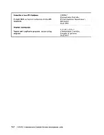
Страница 146: ...n filling in sets Configuration Guide of worksheets The Setup Sheet is used at installation or GA33 0063 customer setup time to plug in the cables and remains with the controller Other worksheets are used for system integration Planning and Site Preparation Prepare for physical installation by planning the site 3720 3721 environment including power requirements Communication Controllers Planning a...

Страница 147: ...n of non IBM Original Equipment Manufacturer s equipment Information GA33 0068 Program Customization 3725 and 3720 3721 Prepare user s application programs Adapt existing Communication Controllers programs Principles of Operation GA33 0013 A 2 3720 3721 Communication Controller Problem Determination Guide ...

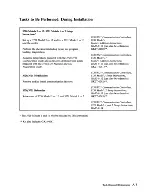
Страница 148: ...f 3720 Model 2 or 12 and 3721 Model 1 or 2 The 3720 Models 1 and 11 will be installed by IBM personnel Kit also includes GA33 0067 3720 3721 Communication Controllers 3720 Modell Feature Addition Instructions GA33 0110 can also be ordered as GK2T 0280 3720 3721 Communication Controllers 3720 Model 11 Feature Addition Instructions GA33 0111 can also be ordered as GK2T 0281 3720 3721 Communication C...

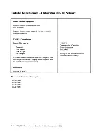
Страница 149: ... Link IPL port LIC weights Save disk contents on backup diskettes Requires Link IPL Requirements and Plugging Sheets prepared with the 3720 3721 Configuration Guide Initialization Initialize 3720 3721 Is also included in the following kits GK2T 0280 GK2T 0281 GK2T 0282 GK2T 0283 3720 3721 Communication Controllers System Integration GA33 0067 A copy of this manual should be available at each conso...

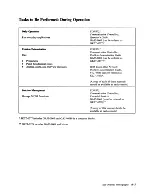
Страница 150: ...mal codes Alarms alerts and NetView messages IBM Token Ring Network Problem Determination Guide SY27 0280 can be ordered as SX27 3710 A copy of each of these manuals should be available at each console Function Management 3720 3721 Communication Controllers Manage MOSS functions Extended Services GA33 0066 must be ordered as GK2T 0278 A copy of this manual should be available at each console SK2T ...

Страница 151: ...A 6 3720 3721 Communication Controller Problem Determination Guide ...

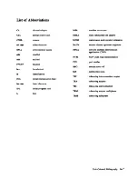
Страница 152: ... problem determination application CNN dsbl disabled NTRI NCP token ring interconnection enbl enabled PJN part number FNCTN function RPO remote power off hex hexadecimal SIA system input area id identification TIC token ring interconnection coupler IML initial microprogram load TRA token ring adapter ins char insert character TRI token ring interconnection IPL initial program load TRM token ring a...

Страница 153: ...A 8 3720 3721 Communication Controller Problem Determination Guide ...

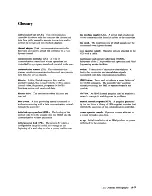
Страница 154: ... initial program load IPL The process by which a configuration image is loaded into storage at the beginning of a work day or after a system malfunction line interface coupler LIC A circuit that attaches up to four communication interface cables to the controller line speed The maximum rate at which signals may be transmitted over a given channel local operator console Operator console attached to...

Страница 155: ...A tO 3720 3721 Communication Controller Problem Determination Guide ...

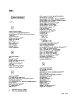
Страница 156: ...y messages channel adapter state function channel adapter trace function NCp channel adapters disabled lamps channel discontact function NCp channel related messages 5 7 codes hexadecimal 7 1 COMM NOT READY 2 2 4 configuration data file CDF console link test 9 1 console logoff console problems local 2 1 remote 2 5 control panel 3720 model I or II 3720 model 2 or 12 control program procedure messag...

Страница 157: ...TION PENDING GOTO instruction 3720 3721 Operator s Guide 3720 3721 Extended Services HALT instruction hazardous port swap hex display hexadecimal codes 7 1 host messages 5 7 how to execute NCP and EP functions IML MOSS with reset from consoles IML MOSS without reset from consoles IML MOSS from control panel IML one scanner messages IML one scanner and immediate function selection immediate functio...

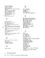
Страница 158: ...S online function MSA MSLA function error codes 3720 3721 Operator s Guide 3720 3721 Extended Services NCP address trace function NCP channel adapter trace function NCP channel discontact function NCP display of register function NCP line test NCP display of storage function NCP dynamic store function NCP functions NCP scanner interface trace SIT NCP transmit control byte NetView messages 6 4 no a...

Страница 159: ...ssages 3720 3721 Operator s Guide 3720 3721 Extended Services reset branch trace function reset branch trace messages reset CCU check function reset CCU function reset CCU LSSD function reset CCU LSSD messages reset I step function reset IOC function resetting logon attempt counters resetting ports responder limitation responder responding controller restore disk from diskettes restoring MCFs save...

Страница 160: ...chment V 25 autocalI V 35 DCE attachment 3720 3721 Operator s Guide 3720 3721 Extended Services VTAM alerts 6 6 WAIT instruction wrap test messages wrap test X 21 DCE attachment X 21 Switched Line Test NCP INumerics I 2740 start stop poll NCP EP 3270 BSe general poll NCP EP 3720 function selection 3720 functions and CCU functions switching between 3720 IPL from the operator console 3720 IPL messag...

Страница 161: ... X 6 3720 3721 Operator s Guide 3720 3721 Extended Services 3720 3721 Communication Controller Problem Determination Guide ...

Страница 162: ... be considered for the next edition of this manual Thank you for taking the time and trouble to fill out this form If you would like a reply please give details overleaf No postage stamp necessary if mailed in the USA Elsewhere an IBM office or representative will be happy to forward your comments or you may mail directly to the address in the Edition Notice on the back of the title page Note Stap...

Страница 163: ...LL BE PAID BY ADDRESSEE International Business Machines Corporation Department 6R1 LG 180 Kost Road Mechanicsburg PA 17055 Plee Do Not Steple Fold and tape NO POSTAGE NECESSARY IF MAILED INTHE UNITED STATES Fold and tape If you would like a reply please print Your Name Company Name Department Street Address Ciry State Zip Code IBM Branch Office serving you ...

Страница 164: ...GA33 BB86 B2 GA33 0086 2 Printed in USA f ...

Отзывы: