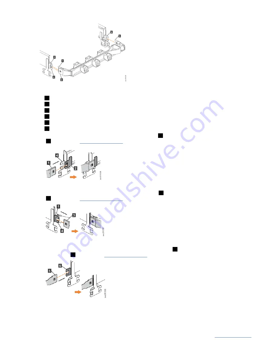
Figure 45. Connectors for the cable management arm
1
Inner connector on upper CMA
2
Connector base on inner rail member
3
Outer connector on upper CMA
4
Connector base on outer rail member
5
Support rail connector on upper CMA
6
Connector base on outer rail member
2. Install the inner connector of the upper CMA assembly (
1
) to the inner member of the left support rail
(
2
), as shown in Figure 46 on page 41.
Figure 46. Install the inner connector of the upper CMA to the inner member of the support rail
3. Install the outer connector of the upper CMA assembly (
3
) to the outer member of the left support rail
(
4
), as shown in Figure 47 on page 41.
Figure 47. Install the outer connector of the upper CMA to the outer member of the support rail
4. Attach the support rail connector on the upper CMA assembly (
5
) to the connector base on the right
support rail (
6
), as shown in Figure 48 on page 41.
Figure 48. Attach the support rail connector of the upper CMA to the right support rail
Ensure the cable-management arm connector attaches securely to the hooks on the rails.
Installing the lower CMA assembly
Note: The procedure for attaching the lower CMA assembly is the same as the procedure to attach the
upper CMA assembly. However, the connector locations are reversed. For comparison, Figure 49 on page
Chapter 2. Installing the system hardware 41
Содержание 2078-4F4
Страница 31: ... Add the fourth expansion directly above the second and so on Chapter 1 Before you begin the installation 7 ...
Страница 129: ......
Страница 130: ...IBM ...


