Unpacking the control enclosure
Before you unpack the FlashSystem 5100 control enclosure, ensure that you review and follow all related
instructions.
Before you begin
Before you start the installation process, complete the information that is requested in the "Planning
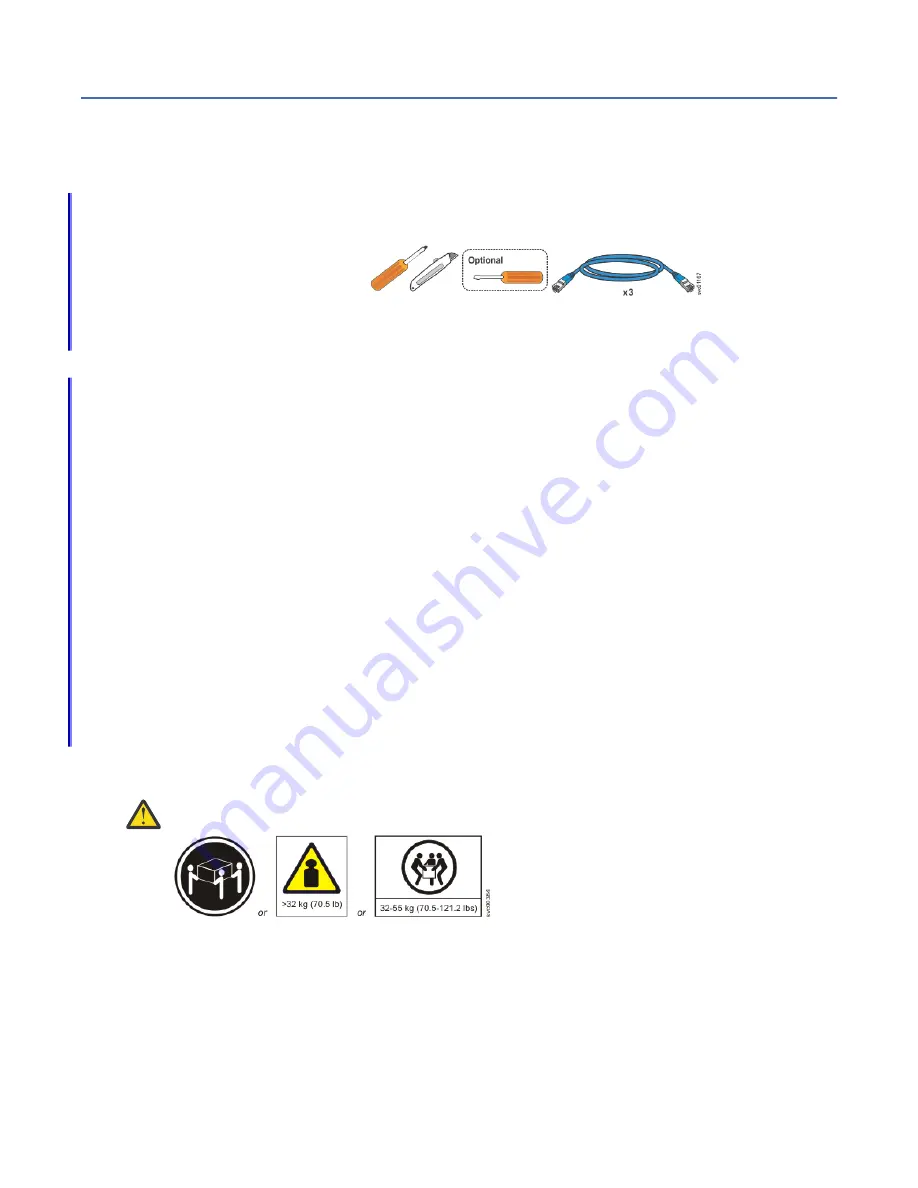
worksheets" in IBM Knowledge Center and ensure the following items are available.
• Philips screw driver
• Box knife
• Flat-blade screw driver
(optional)
• Three Ethernet cables
The control enclosure and the following related parts are included in one box. The enclosed inventory
sheet lists the part numbers of the items that were ordered. Items, such as drives and networking
adapters, are preinstalled inside each node canister.
• Control enclosure with the following components preinstalled:
– Two node canisters with optional networking adapters, SFPs, and memory
Each node canister contains two networking adapter slots. The same number and type of adapters
must be installed in each node canister. The control enclosure can contain 0, 2, or 4 networking
adapters.
– Two power supply units (PSUs)
– A combination of 24 drives and drive blanks
The number of drives and drive blanks varies, according to the number of drives that were specified
in the product order. For example, if 12 drives were ordered, the drives and 12 drive blanks are
preinstalled in the control enclosure.
• Rail kit, which includes the left and right rails, and 8 securing M5 screws and locating pins.
• Cables, if they were ordered, for the type and number of networking adapters that are installed in each
node canister.
• Two power cables.
About this task
CAUTION: The weight of this part or unit is between 32 and 55 kg (70.5 and 121.2 lb). It takes
three persons to safely lift this part or unit. (C010)
To unpack the control enclosure, complete the following steps. If three persons or a lift are not available,
more steps are required to remove some parts before the control enclosure can be installed.
1. Cut the box tape and open the lid of the shipping carton.
2. Remove the rail kit box and set it aside in a safe location.
3. Lift the front and rear foam packing pieces from the carton.
4. Remove the four corner reinforcement pieces from the carton.
10 FlashSystem 5100 : Quick Installation Guide for MTM 2078-4F4, 2078-4H4, 2078-12G, 2078-AFG,
2078-24G, 2078-A9G, 2078-92G, and 2078-UHB
Содержание 2078-4F4
Страница 31: ... Add the fourth expansion directly above the second and so on Chapter 1 Before you begin the installation 7 ...
Страница 129: ......
Страница 130: ...IBM ...


