IBEX TX31 Скачать руководство пользователя страница 2

INSTALLATION GUIDE


2022-1.0 


IBEX EQUIPMENT CO 


Figure 3 


Figure 4 


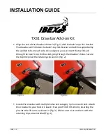
Align the crossbar where it can be placed inside the opening of the drawbar’s 

hitch pin receiver. Once aligned, install the pin and washer from the top and the 

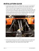
washer and retaining clip from the bottom as shown in (Fig. 5). Raise the 3-point 

hitch to remove the weight of the baler from the support stand. Lift the support 

stand and secure it with the retaining clip as seen in (Fig. 6). 


Figure 5 


Figure 6 


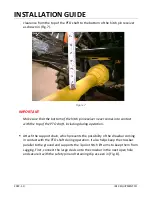
Attach the new, longer PTO shaft that came with the drawbar kit to the baler 

and then to the tractor. Ideally, you should have a minimum of 3 inches of 

Содержание TX31

Страница 1: ... aligned you can insert the top link pin through the baler s top link bracket going through the drawbar s holes Secure the top link pin with a retaining clip seen in Fig 2 Figure 1 Figure 2 Locate the crossbar with multiple holes and category 1 pins on each end Attach this crossbar to your tractor s lower three point hitch lift arms by inserting the pins into the lift arms as shown in Fig 3 Make s...

Страница 2: ...om the top and the washer and retaining clip from the bottom as shown in Fig 5 Raise the 3 point hitch to remove the weight of the baler from the support stand Lift the support stand and secure it with the retaining clip as seen in Fig 6 Figure 5 Figure 6 Attach the new longer PTO shaft that came with the drawbar kit to the baler and then to the tractor Ideally you should have a minimum of 3 inche...

Страница 3: ...ith the top of the PTO shaft including during operation Attach the support chain which prevents the possibility of the drawbar coming in contact with the PTO shaft during operation It also helps keep the crossbar parallel to the ground and supports the 3 point hitch lift arms to keep them from sagging First connect the large clevis onto the crossbar in the next open hole and secure it with the saf...

Страница 4: ...or s top link brackets using one of the smaller clevises as shown in Fig 9 Then thread the chain through the larger clevis and then back to the other top link bracket on the tractor Attach the second smaller clevis to the other top link bracket Select a different chain link as needed to ensure that the chain is mostly snug as seen in Fig 9 Figure 9 ...

Страница 5: ... components and cause serious harm or damage to equipment and or people Make sure that you still have a minimum of 3 inches of clearance between the top of the PTO shaft and the bottom of the hitch pin receiver as mentioned earlier If not reinstall the chain with a shorter length by selecting a different link Figure 10 The kit comes with longer pull ropes for the tailgate release and net feeding f...

Отзывы: