


11.2.2 Miscellaneous issues
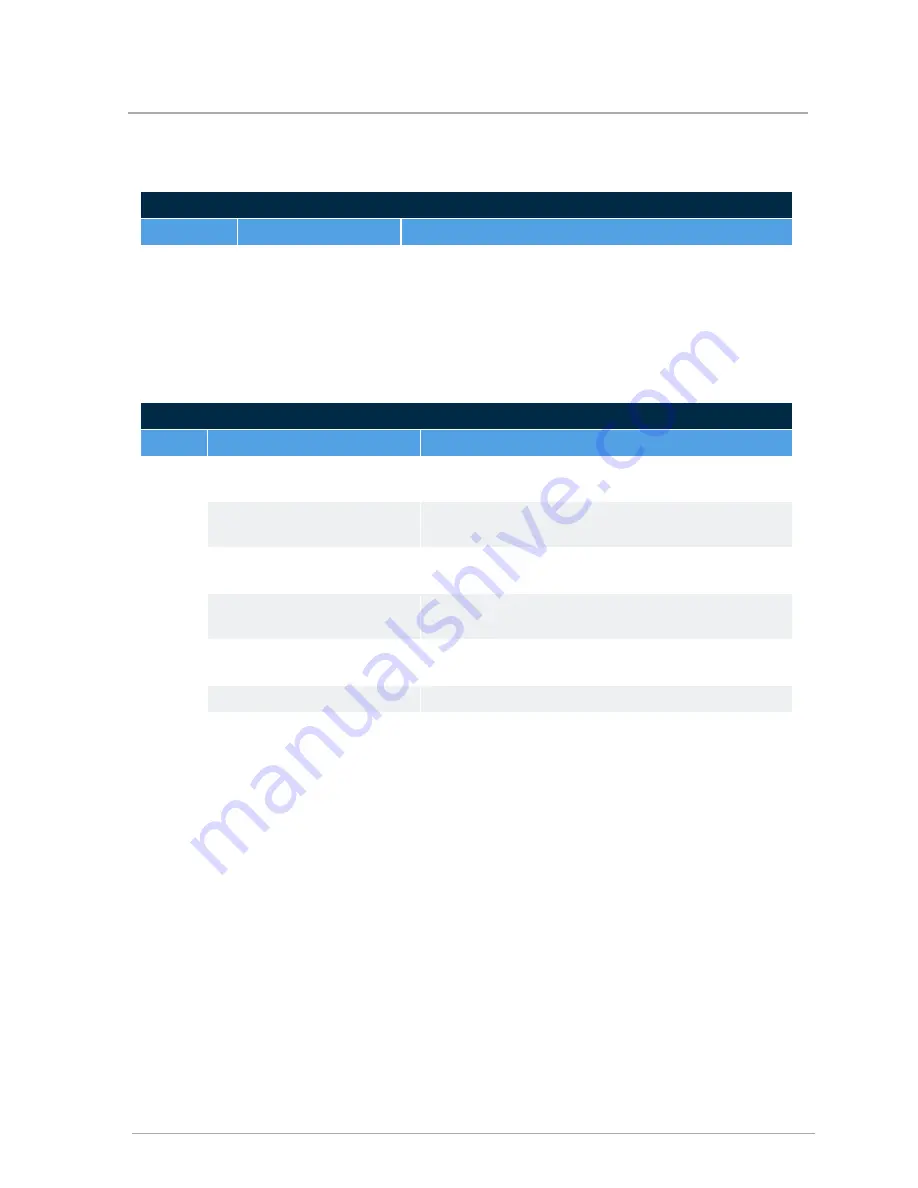
Miscellaneous issues
Issue
Diagnosis
Fix
‘Ghost’ call
for heat.
Triac or ‘Power-
robbing’ thermostat
sending current to
boiler.
Remove CN2 connections from boiler to confirm that stray
voltage, or current induced in thermostat wiring, is source
of nuisance signal. Replace the Power Robbing
thermostat or isolate the thermostat with a relay.
11.2.3 Cycling issues
Cycling issues
Issue
Diagnosis
Fix
Rapid
Cycling
Incorrect settings or defective
thermostat.
Check operation. Refer to manufacturer’s instructions.
Check setting with ammeter.
Air in system or marginal water
flow.
Bleed/purge system as required. Confirm temp rise in
the heat exchanger.
Low water flow due to
improper piping.
Review pressure drop of boiler piping.
Low water flow due to
restrictions in water pipe.
Check temperature differential across zone/heat
exchanger.
Low radiation.
Check actual amount of radiation per zone and refer to
manufacturer’s rating tables.
Appliance Oversized.
Check load calculation vs. minimum boiler output.
Improperly set or defective
controls.
Check operation with ohmmeter/voltmeter.
59
11.2.2 Miscellaneous issues
Содержание EBX Series
Страница 10: ...Intentionally left empty 10 Section Specifications ...
Страница 11: ...11 Connection specifications ...
Страница 12: ...Intentionally left empty ...
Страница 14: ...4 3 Internal view 14 Section Introduction ...
Страница 16: ...Intentionally left empty ...
Страница 18: ...Intentionally left empty ...
Страница 48: ...Intentionally left empty ...
Страница 50: ...Intentionally left empty ...
Страница 60: ...Intentionally left empty ...
Страница 61: ...61 Appendices Wiring diagrams Figure 29 EBX series Boilerinternal wiring diagram ...
Страница 62: ...Intentionally left empty ...
Страница 63: ...63 ...