background image


10 

SI-614 / SI-614-M User Manual 


2.1.4 

Mounting Installation 

Requirements 


Before mounting the system, ensure that you have enough room for the power 
adaptor and signal cable routing, and have good ventilation for the power 
adaptor. The method of mounting must be able to support weight of the SI-
61S plus the weight of the suspending cables attached to the system. Use the 
following methods for mounting your system: 


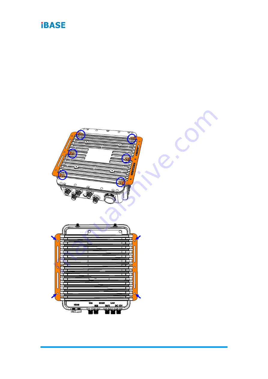
Wall Mounting Installation 


1.  Turn your device upside down. Attach the wall-mount kit (2 brackets) to 

the device and secure with the supplied 6 screws. 


2.  Prepare at least 4 screws (M3) to install the device on the wall as shown. 


dra

ft

Содержание SW-101-N

Страница 1: ...SW 101 N Outdoor Waterproof Digital Signage Player User s Manual Version 1 0 Apr 2019 d r a f t...

Страница 2: ...the products described in this document without prior notice Every effort has been made to ensure the information in the document is correct however IBASE does not guarantee this document is error fr...

Страница 3: ...r s instructions may cause harmful interference to radio communications WEEE This product must not be disposed of as normal household waste in accordance with the EU directive of for waste electrical...

Страница 4: ...current may still flow Use neutral cleaning agents or diluted alcohol to clean the device chassis with a cloth Then wipe the chassis with a dry cloth Vacuum the dust with a computer vacuum cleaner to...

Страница 5: ...THAT FAIL DUE TO MISUSE ACCIDENT IMPROPER INSTALLATION OR UNAUTHORIZED REPAIR SHALL BE TREATED AS OUT OF WARRANTY AND CUSTOMERS SHALL BE BILLED FOR REPAIR AND SHIPPING CHARGES Technical Support Servic...

Страница 6: ...ent 8 2 1 1 Memory 8 2 1 2 Mini PCIe Cards 9 2 1 3 WiFi 3G 4G Antenna Installation 9 2 1 4 Mounting Installation 10 2 2 Pinout for DC Power Input Connector 11 2 3 Pinout for Digital I O Connector 12 2...

Страница 7: ...3 5 LAN Driver Installation 28 3 6 Intel Trusted Execution Engine Drivers Installation 29 Chapter 4 BIOS Setup 30 4 1 Introduction 31 4 2 BIOS Setup 31 4 3 Main Settings 32 4 4 Advanced Settings 33 4...

Страница 8: ...1 Chapter 1 General Information The information provided in this chapter includes Features Packing List Accessories Specifications Overview Dimensions d r a f t...

Страница 9: ...n as well Aside from being fanless the unit has a wide operating temperature range of 40 C 75 C The SW 101 N supports IBASE unique iControl and Observer technologies for intelligent control and remote...

Страница 10: ...3 pin terminal connector LAN Cable M12 female to RJ45 USB 2 0 Cable M12 female to USB 2 0 Digital I O Cable M12 female to open wire Serial Cable M12 female to D Sub9 1 5 Specifications Product SW 101...

Страница 11: ...r Digital I O 1 x 4 In 4 Out Digital I O M12 to open wire Antenna 2 x Antenna openings for jack type with waterproof design Expansion 1 x Mini PCIe half full size for WiFi 3G 4G LTE options 1 x Mini P...

Страница 12: ...view Front View No Name No Name 1 Antenna Holes 2 Wall Mounting Kit Rear View No Name No Name 1 HDMI Port C3 4 Digital I O Port M12 to open wire 2 USB 2 0 Ports M12 5 GbE LAN Port M12 3 COM RS 232 Por...

Страница 13: ...6 SI 614 SI 614 M User Manual Oblique View 1 7 Dimensions Unit mm d r a f t...

Страница 14: ...7 Chapter 2 Hardware Installation Motherboard Information The information provided in this chapter includes Installation or replacement Information and locations of connectors d r a f t...

Страница 15: ...form the following steps 1 Press the ejector tab of the memory slot down and outwards with your fingertips 2 Hold the memory module and align the key of the module with that on the memory slot 3 Gentl...

Страница 16: ...Fix the M 2 network card with an M3 screw 2 1 3 WiFi 3G 4G Antenna Installation Thread the WiFi 3G 4G antenna extension cable through an antenna hole of the front I O cover and fasten the antenna as s...

Страница 17: ...daptor The method of mounting must be able to support weight of the SI 61S plus the weight of the suspending cables attached to the system Use the following methods for mounting your system Wall Mount...

Страница 18: ...Connector DC Power Input Cable M12 to 3 pin terminal block DC power input cable is optional for purchase M12 end Pin Signal Name Pin Signal Name 1 Voltage 2 Voltage 3 NC 4 Ground Terminal block end P...

Страница 19: ...O Connector Digital I O Cable M12 to open wire Digital I O cable is optional for purchase M12 end Open Wire end Pin Signal Name Pin 1 IN0 User self defined 2 Ground 3 IN1 4 Ground 5 IN2 6 Ground 7 IN...

Страница 20: ...SI 614 M User Manual 13 2 2 4 Pinout for COM1 RS 232 Port Seral Cable M12 to D Sub9 Serial cable is optional for purchase M12 end D Sub end Pin Signal Name Pin 1 1 2 RxD 2 3 TxD 3 4 4 5 Ground 5 6 6...

Страница 21: ...a non conductive base mounted on the circuit board Jumper caps are used to have the functions and features enabled or disabled If a jumper has 3 pins you can connect either PIN1 to PIN2 or PIN2 to PIN...

Страница 22: ...Hardware Configuration SI 614 SI 614 M User Manual 15 2 2 6 Jumper Connector Locations on Motherboard Motherboard SGT MB2 SGT MB2 top and I O d r a f t...

Страница 23: ...s Quick Reference Function Connector Name Page Clearing CMOS Data JP4 16 Clearing ME Register JP5 17 Factory Use Only JP1 JP2 JP3 2 7 1 Clearing CMOS Data JP4 Function Pin closed Illustration Normal d...

Страница 24: ...Hardware Configuration SI 614 SI 614 M User Manual 17 2 2 7 2 Clearing ME Register JP5 Function Pin closed Illustration Normal default 1 2 Clear ME 2 3 1 1 1 d r a f t...

Страница 25: ...J9 left J10 right 20 COM RS 232 Connector J11 J12 20 LAN Connector J13 21 HDMI Connector J14 J15 21 Digital I O Connector J16 22 System Fan Power Connector SYS_FAN1 22 Power Button SW1 Power LED Indi...

Страница 26: ...19 2 2 8 2 5V Power Connector J1 Pin Signal Name Pin Signal Name 1 5V 2 Ground 2 8 3 RTC Battery Connector J3 Pin Signal Name Pin Signal Name 1 Battery 2 Ground 2 8 4 Reset Connector J8 Pin Signal Nam...

Страница 27: ...Speaker right J9 Speaker left Pin Signal Name Pin Signal Name 1 SPK L 2 SPK L J10 Speaker right Pin Signal Name Pin Signal Name 1 SPK R 2 SPK R 2 8 6 COM RS 232 Connector J11 J12 Pin Signal Name Pin...

Страница 28: ...MDI1 7 MDI0 8 MDI0 2 8 8 HDMI Connector J14 J15 Pin Signal Name Pin Signal Name 1 TMDS_DATA2_P 2 TMDS_DATA2_N 3 Ground 4 Ground 5 TMDS_DATA1_P 6 TMDS_DATA1_N 7 Ground 8 Ground 9 TMDS_DATA0_P 10 TMDS_D...

Страница 29: ...n Signal Name Pin Signal Name 1 IN0 2 Ground 3 IN1 4 Ground 5 IN2 6 Ground 7 IN3 8 Ground 9 IN4 10 Ground 11 IN5 12 Ground 13 IN6 14 Ground 15 OUT1 16 Ground 2 8 10 System Fan Power Connector SYS_FAN1...

Страница 30: ...apter 3 Driver Installation The information provided in this chapter includes Intel Chipset Software Installation Utility Graphics Driver HD Audio Driver Intel Trusted Execution Engine LAN Driver d r...

Страница 31: ...s operating system you must install the Intel Chipset Software Installation Utility first before proceeding with the drivers installation 3 2 Intel Chipset Software Installation Utility The Intel Chip...

Страница 32: ...I 614 SI 614 M User Manual 25 3 3 Accept the license agreement and proceed with the installation process 4 Click Install 5 When the driver is completely installed restart the computer for changes to t...

Страница 33: ...M User Manual 3 3 Graphics Driver Installation 1 Run the Setup exe file 2 On the Welcome screen click Next 3 Accept the license agreement and click Yes to continue 4 On the Readme File Information cli...

Страница 34: ...the driver is completely installed restart the computer for changes to take effect 3 4 HD Audio Driver Installation 1 Run the Setup exe file 2 On the Welcome screen of the InstallShield Wizard click N...

Страница 35: ...3 5 LAN Driver Installation 1 Run the Setup exe file 2 On the Welcome screen of the InstallShield Wizard click Next 3 Click Install 4 When the driver is completely installed restart the computer for c...

Страница 36: ...s Installation 1 Run the Setup exe file 2 When the Welcome screen appears click Next 3 Accept the license agreement and click Next for installation 4 Click Next until the installation starts 5 As the...

Страница 37: ...describes the different settings available in the AMI BIOS that comes with the board The topics covered in this chapter are as follows Main Settings Advanced Settings Chipset Settings Security Settin...

Страница 38: ...routines thus preventing you from invoking the Setup You can also press F7 to call the pop up Boot menu immediately If you still need to enter Setup restart the system by pressing the Reset button or...

Страница 39: ...User Manual 4 3 Main Settings BIOS Setting Description System Date Sets the date Use the Tab key to switch between the data elements System Time Set the time Use the Tab key to switch between the data...

Страница 40: ...y PXE OpROM ACPI Settings Displays the system ACPI parameters iSmart Controller Sets up the power on time for the system Super IO Configuration Displays the parameters of the system Super I O chip HW...

Страница 41: ...nables Disables BIOS ACPI Auto configuration Enable Hibernation Enables Disables system ability to hibernate OS S4 Sleep State This option may not be effective with some operating systems ACPI Sleep S...

Страница 42: ...delay Temperature Guardian Generates the reset signal when system hands up on POST Schedule Slot 1 2 Sets up the hour minute for system powe on Important If you would like to set up a schedule between...

Страница 43: ...g Description Watchdog Control Controls the Watchdog Options Disabled 30 sec 60 sec 90 sec 120 sec Serial Port 1 2 Configuration Sets parameters of Serial Port 1 2 COMA COMB Enables Disables the seria...

Страница 44: ...Description Serial Port Enables Disables serial port COM Change Settings Selects an optimal settings for Super I O device Options Auto IO 3F8h IRQ 4 IO 3F8h IRQ 3 4 5 6 7 9 10 11 12 IO 2F8h IRQ 3 4 5...

Страница 45: ...es serial port COM Change Settings Selects an optimal settings for Super I O device Options Auto IO 3E8h IRQ 3 IO 3E8h IRQ 3 4 5 6 7 9 10 11 12 IO 2E8h IRQ 3 4 5 6 7 9 10 11 12 IO 2F0h IRQ 3 4 5 6 7 9...

Страница 46: ...rature Disables or sets system shutdown temperature to 70 C 75 C 80 C 85 C 90 C or 95 C Temperatures Voltages These fields are the parameters of the hardware monitoring function feature of the motherb...

Страница 47: ...M User Manual 4 4 5 CPU Configuration BIOS Setting Description Socket 0 CPU Information Socket specific CPU Information 4 4 6 PPM Configuration BIOS Setting Description EIST Enables Disables Intel Spe...

Страница 48: ...scription Serial ATA SATA Enables Disables Serial ATA SATA Speed Support Selects SATA speed support as Gen 1 or Gen SATA Mode Selects the SATA mode as IDE or AHCI Serial ATA Port 1 Enables Disables Se...

Страница 49: ...ld be claimed by EHCI driver USB Mass Storage Driver Support Enables Disables the support for USB mass storage driver Port 60 64 Emulation Enables I O port 60h 64h emulation support This should be ena...

Страница 50: ...BIOS Setup SI 614 SI 614 M User Manual 43 4 4 5 Chipset Settings BIOS Setting Description North Bridge Displays the parameters of North Bridge d r a f t...

Страница 51: ...44 SI 614 SI 614 M User Manual 4 6 Security Settings BIOS Setting Description Administrator Password Sets an administrator password for the setup utility User Password Sets a user password d r a f t...

Страница 52: ...et Boot Enables Disables Quiet Boot option Fast Boot Enables Disables boot with initialization of a minimal set of devices required to launch active boot option Has not effect for BBS boot options Boo...

Страница 53: ...r saving the changes Discard Changes and Reset Resets system setup without saving any changes Save Changes Saves changes done so far to any of the setup options Discard Changes Discards changes done s...

Страница 54: ...ix This section provides the mapping addresses of peripheral devices and the sample code of watchdog timer configuration I O Port Address Map Interrupt Request Lines IRQ Watchdog Timer Configuration d...

Страница 55: ...7 0x00000067 Motherboard resources 0x00000070 0x00000070 Motherboard resources 0x00000070 0x00000070 System CMOS real time clock 0x00000080 0x0000008F Motherboard resources 0x00000092 0x00000092 Mothe...

Страница 56: ...ogrammable interrupt controller 0x00000028 0x00000029 Programmable interrupt controller 0x0000002C 0x0000002D Programmable interrupt controller 0x00000030 0x00000031 Programmable interrupt controller...

Страница 57: ...IRQ 4294967291 Intel R Trusted Execution Engine Interface IRQ 8 High precision event timer IRQ 4294967294 Standard SATA AHCI Controller IRQ 4 Communications Port COM1 IRQ 5 Communications Port COM2 I...

Страница 58: ...before the timer counts to zero 1 Sample Code The file NCT5523D H THIS CODE AND INFORMATION IS PROVIDED AS IS WITHOUT WARRANTY OF ANY KIND EITHER EXPRESSED OR IMPLIED INCLUDING BUT NOT LIMITED TO THE...

Страница 59: ...nclude stdio h include stdlib h include NCT5523D H int main void void WDTInitial void void WDTEnable unsigned char void WDTDisable void int main void char SIO SIO Init_NCT5523D if SIO 0 printf Can not...

Страница 60: ...0x30 0x01 enable timer bBuf Get_NCT5523D_Reg 0xF0 bBuf 0x08 Set_NCT5523D_Reg 0xF0 bBuf count mode is second Set_NCT5523D_Reg 0xF1 NewInterval set timer void WDTDisable void Set_NCT5523D_LD 0x08 switch...

Страница 61: ...d Lock_NCT5523D void unsigned int Init_NCT5523D void unsigned int result unsigned char ucDid NCT5523D_BASE 0x4E result NCT5523D_BASE ucDid Get_NCT5523D_Reg 0x20 if ucDid 0xC4 NCT5523D goto Init_Finish...

Страница 62: ...T LD Lock_NCT5523D void Set_NCT5523D_Reg unsigned char REG unsigned char DATA Unlock_NCT5523D outportb NCT5523D_INDEX_PORT REG outportb NCT5523D_DATA_PORT DATA Lock_NCT5523D unsigned char Get_NCT5523D...

Отзывы: