


Hardware Configuration
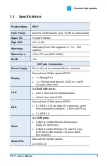
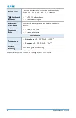
IP417
User’s Manual
17
2
•
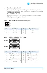
Reset Switch (Pins 5 and 6)
The reset switch allows you to reset the system without turning the main
power switch off and then on again. Orientation is not required when making
a connection to this header.
•
Power LED (Pins 7 and 8)
This connector connects to the system power LED on control panel. This
LED will light when the system turns on.
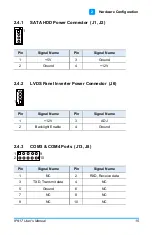
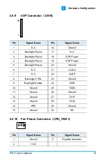
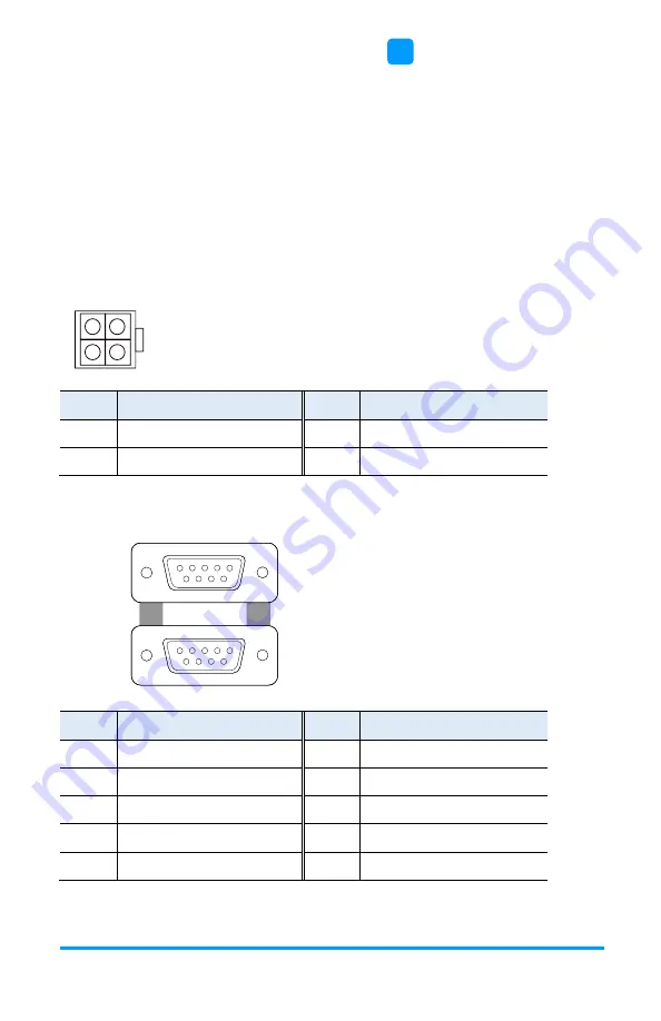
2.4.6
DC-In 12V Power Connector (J14)
3
4
1
2
Pin
Signal Name
Pin
Signal Name
1
Ground
3
+12V
2
Ground
4
+12V
2.4.7
COM1 & COM2 Ports (CN2)
COM1:
COM2:
1
6
5
9
1
6
5
9
Pin
Signal Name
Pin
Signal Name
1
DCD, Data carrier detect
6
DSR, Data set ready
2
RXD, Receive data
7
RTS, Request to send
3
TXD, Transmit data
8
CTS, Clear to send
4
DTR, Data terminal ready
9
RI, Ring indicator
5
Ground
Содержание IP417
Страница 1: ...IP417 Mini ITX COM Express Type 10 R3 0 Carrier Board User s Manual Version 1 0 July 2019...
Страница 8: ...viii IP417 User s Manual This page is intentionally left blank...
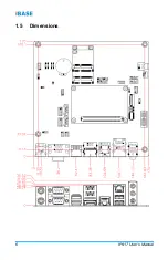
Страница 14: ...6 IP417 User s Manual 1 5 Dimensions...
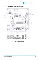
Страница 17: ...Hardware Configuration IP417 User s Manual 9 2 2 2 Connector Locations on IP417 Board diagram of IP417...
Страница 28: ...20 IP417 User s Manual This page is intentionally left blank...


