


14
IP417 U
ser’s Manual
2.4
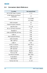
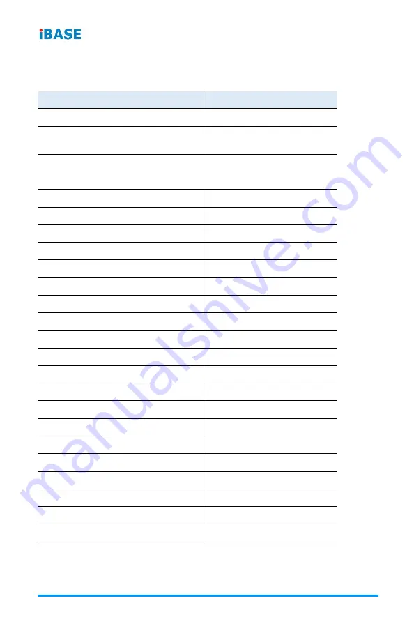
Connectors Quick Reference
Function
Connector Name
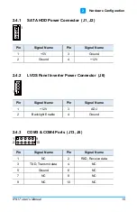
SATA HDD Power Connector
J1, J2
LVDS Panel Inverter Power
Connector
J6
COM3 & COM4 Ports
J13 (COM3)
J8 (COM4)
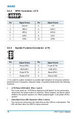
GPIO Connector
J17
System Function Connector
J11
Mini-PCIe Slot
J12, J15
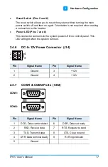
DC-In 12V Power Connector
J14
DisplayPort
CN1
COM1 & COM2 RS-232 Ports
CN2
USB 3.0
CN3
PS/2 Keyboard & Mouse
CN4
Audio Connector
CN5
GbE LAN Port
CN6, CN8
USB 2.0
CN7
SATA 3 Connector
CN9, CN11
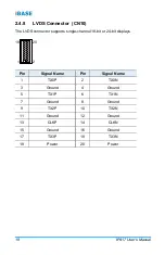
LVDS Connector
CN10
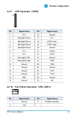
eDP Connector
CN15
COMe Connector
RECS1
PCIe (x1) Slot
PCIEX1
Fan Power Connector
CPU_FAN1
Power Button
SW2
Reset Button
SW1
Factory Use Only
J3, J10
Содержание IP417
Страница 1: ...IP417 Mini ITX COM Express Type 10 R3 0 Carrier Board User s Manual Version 1 0 July 2019...
Страница 8: ...viii IP417 User s Manual This page is intentionally left blank...
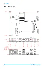
Страница 14: ...6 IP417 User s Manual 1 5 Dimensions...
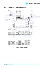
Страница 17: ...Hardware Configuration IP417 User s Manual 9 2 2 2 Connector Locations on IP417 Board diagram of IP417...
Страница 28: ...20 IP417 User s Manual This page is intentionally left blank...


