background image

Page 15                                                                      2019-05-10                                                     

[email protected]


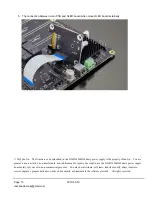
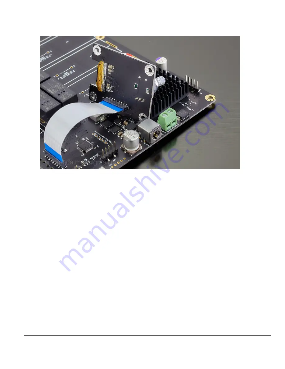
5.  The connection between main PCB and OLED board when move OLED board externally 


© 2019 Ian Jin.    The firmware code embedded in the LifePO4 MkIII battery power supply is the property of Ian Jin.    You are 

granted a non-exclusive, non-transferable, non-sublicenseable, royalty-free right to use the LifePO4 MkIII battery power supply 

board solely for your own, non-commercial purposes.    You may not distribute, sell, lease, transfer, modify, adapt, translate, 

reverse engineer, prepare derivative works of, decompile, or disassemble the software provided.    All rights reserved. 

Содержание LifePO4 MkIII

Страница 1: ...er supply board in a fire proof container Also has to make sure the power adapter is disconnected 6 Please follow other common battery safety instructions 7 Have to use 80W or higher power iron to sol...

Страница 2: ...panel Programmable screensaver function to protect OLED from screen burn in Can use either 26650 battery cells with tabs or standard 26650 battery holders D LifePO4 MkIII new improvements Ready for up...

Страница 3: ...Page 3 2019 05 10 iancanada mail gmail com...

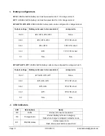
Страница 4: ...or battery holders to BT1 BT2 BT3 BT4 BT5 BT8 BT9 and BT10 or configure battery cells accord to the required voltages Jumper wires may also be required Please refer to battery configuration section f...

Страница 5: ...nected to J5 J1 3 3V pure battery output voltage rail in 2 pin 5 0mm terminal This output is galvanic isolated from all other output and input It comes with over current and over discharge protections...

Страница 6: ...r normal digital sections before isolator It s not recommended for sensitive audio circuits like DAC clock and I V stage This output is not galvanic isolated from DC input This output can be disabled...

Страница 7: ...All other pins reserved please keep un connected 9600 N 8 1 J13 Micro USB socket reserved for future applications or FW upgrade J30 5V output to UcMateConditioner Internally connected to J8 J29 ON OFF...

Страница 8: ...BT10 BT9 TP7 TP8 short 6 6V BT2 BT10 TP9 TP10 short 3 3V BT2 TP11 TP12 short 0V Non Non BT5 BT4 BT3 BT1 26650 LifePO4 battery cells can be configured for voltage rail at J3 Output voltage Battery cell...

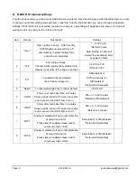
Страница 9: ...sabled into standby mode when this voltage is reached 3 25V to 3 75V Default 3 35V 3 5V To enable continuous disable the 5V linear voltage rail EN enabled or CON continuous or DIS disabled Default is...

Страница 10: ...or more than 2 seconds 3 Extern on off control signal changing from 0V to 3 3V 6V will turn on the power 2 How to turn off the power supply There are 3 ways to turn on the power supply 1 Press and hol...

Страница 11: ...oard with the main PCB through the supplied 10 pin FFC cable from J9 to J14 Please see the picture Connection between main PCB and external OLED board for the orientation of cable Reversing the FFC FP...

Страница 12: ...mes may fall into audible frequency range though it still fully functional To fix this issue you can just simply replace it with a higher voltage power supply say a standard 18 5V laptop adapter or hi...

Страница 13: ...Page 13 2019 05 10 iancanada mail gmail com 1 LifePO4 MkIII power supply 2 LifePO4 MkIII power supply with battery holders and batteries...

Страница 14: ...Page 14 2019 05 10 iancanada mail gmail com 3 Upgrade to ultra capacitor power supply by UcMateConditioer UcHybrid and UcAdpater 4 LifePO4 power supply integrates with DAC system...

Страница 15: ...er supply is the property of Ian Jin You are granted a non exclusive non transferable non sublicenseable royalty free right to use the LifePO4 MkIII battery power supply board solely for your own non...

Отзывы: