


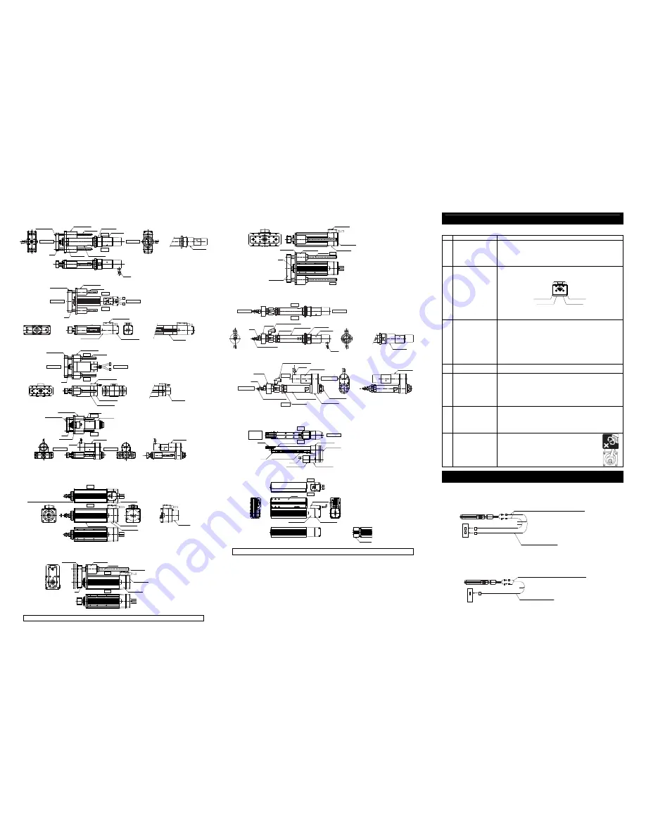
[RGD3C, RGD3D, RGD4C, RGD4D]
There are no brake-equipped types for RGD3D and RGD4D.
[RGD5C]
[RGD7AD, RGD7BD]
[RGD3R, RGD4R]
2.2.2 Short Length Type
[SRA4R, SRGS4R, SRGD4R]
The appearance is the same as RCP2-SRA4R, SRGS4R and SRGD4R.
[SRA7BD]
[SRGS7BD]
The appearance should be the same for the brake-equipped type.
For the details of dimensions and outlines, refer to the catalog or Instruction Manual (DVD).
[SRGD7BD]
The appearance should be the same for the brake-equipped type.
2.2.3 Dust and Splash-Proof Type
[RA3C, RA3D, RA4C, RA4D]
There are no brake-equipped types for RA3D and RA4D.
[RA3R, RA4R]
3. Arm Type
3.1 RCA,
RCS2
[A4R, A5R, A6R]
Equipped with brake
4. Flat Type
4.1 RCS2
[F5D]
For the details of dimensions and outlines, refer to the catalog or Instruction Manual (DVD).
Attachment
Refer to the Instruction Manual (DVD) for the attachments of the actuator and loads.
[Precautions for Attachments]
No.
Item
Precautions
1 Installation
•
Installing the slider type actuator with to horizontally oriented wall mount or ceiling mount
may cause the stainless steel sheet to be slacked or off the right position. Continued use of
the actuator with this condition may result in the breakage of the stainless steel sheet.
Adjust the sheet tension accordingly in the regular inspection.
(Refer to the maintenance section on the Instruction Manual for the procedure of stainless
steel sheet tension adjustment.)
•
Avoid using the actuator with no brake in the vertical orientation.
2 Attachment
Surface
•
The base has to have a structure with sufficient rigidity to prevent oscillation.
•
The side and the bottom surfaces of the base of the slider type actuator are the datum for
the slider drive. If accuracy for its run is required, use these surfaces as a datum of the
installation.
Reference Surface
(Side of Base)
Reference Surface
Reference Surface
Reference Surface
(Side of Base)
•
The actuator mounting surface and other surfaces that are used as a datum should be flat
enough with an accuracy of machining or equivalent treatment, and the flatness of the
mounting surface needs to be 0.05mm/m or less.
•
Secure the space where maintenance work can be performed.
3
Bolt to be used
•
For the bolts to be used, a high-tensile bolt complying with ISO-10.9 or more is recommended.
•
If using the tapped holes, use screws with the thread length dimension being less than the
effective depth of the holes.
•
In case the tapped hole is a through hole, be careful so the screw tip does not exceed the
surface of the tapped hole.
•
For the actuator mounting, use a bolt with the dimension of its effective mating length to the
tapped hole is as stated below.
If tapped hole on steel
→
thread length same as nominal diameter
If tapped hole on aluminum
→
thread length 1.8 times longer than nominal diameter
•
When using a foot base for installation to a platform or equivalent, in order to protect the
foot base, apply washers dedicated for high-tensile bolt if using bolts of M8 or larger. No
washer is needed for M6 or smaller bolts. Also, do not use a normal washer.
4 Tightening
Torque
•
Please follow the specification values stated in the Instruction Manual (DVD) for the
tightening torque. Failure to do so may cause an operation problem.
5
Load Moment and Overhung
length
•
Please follow the specification values stated in the Instruction Manual (DVD) for the load
moment and the overhung length.
Failure to do so may cause abnormal vibration or noise, and also may remarkably shorten
the product life.
•
Please do not apply any external force from other than rod moving direction (radial load) to
the rod.
Any perpendicular or radial force to the rod may cause damage to the actuator or operation
problem.
Use an actuator with a guide or equip the actuator with an optional guide if the
actuator receives an external force from the direction other than its moving direction.
6 Stainless
sheet
•
Please do not hold the stainless steel sheet directly with hands. Please, also, be careful not
to make a dent on the stainless steel sheet. Stainless sheet is easy to get dented because it
is thin. Using it with a dent on may cause a breakage.
•
If there is dust or metal contamination attached on the stainless steel sheet, please wipe it
off the sheet surface. Operation with the stainless sheet that has foreign matters on its
surface may cause problems such as sheet damage, waviness, etc. inside the slider.
•
Please do not operate the unit in the ambient with dust or metal contamination.
7
Load Attachment to Rod
•
Do not apply rotation torque on the rod
(slide shaft). It may cause damage inside.
•
Tighten the nut on the rod tip with holding
the rot with a wrench or an equivalent tool.
Wiring
For the controller, only the dedicated controller manufactured by our company can be used.
For the connection between the actuator and controller, use the attached dedicated connection cable.
1. RCP2, RCP2CR, RCP2W Actuator
[Connection to the PCON (other than PCON-CA), PSEL controller]
Dedicated Connection Cable
•
Motor Cable (Robot Cable) CB-RCP2-MA
□□□
•
Encoder Cable CB-RCP2-PB
□□□
/Encoder Cable Robot Cable CB-RCP2-PB
□□□
-RB
□□□
shows the cable length. The max. length should be 20m. Example) 080
=
8m
[Connection to the PCON-CA, PMEC, PSEP controller, etc]
Dedicated Connection Cable
•
Motor Encoder Cable CB-PSEP-MPA
□□□
□□□
shows the cable length. The max. length should be 20m. Example) 080
=
8m
Right
Left
Guide Bracket
Guide Bearing
Guide Rod
Head Cover
Motor Unit
Motor Side
Rod Side
Rod
Rod Cover
Cylinder Tube
Cable
Brake Unit
Right
Left
Motor Side
Rod Side
Guide Bracket
Guide Bearing
Guide Rod
Rod
Connector Box
Encoder Cover
Motor Housing
Brake Unit
Right
Left
Motor Side
Rod Side
Guide Bracket
Guide Bearing
Guide Rod
Rod
Connector Box
Encoder Cover
Motor Housing
Brake Unit
Right
Left
Guide Bearing
Guide Bracket
Guide Rod
Head Cover
Motor Unit
Rod Cover
Rod
Cable
Motor Side
Rod Side
Brake Unit
Home Position Adjustment Screws (2 places)
Do not touch these screws.
Connector Box
Right
Left
Encoder Cover
Motor Housing
Aluminum Frame
Brake Unit
Right
Left
Guide Bracket
Guide Bearing
Guide Rod
Connector Box
Encoder Cover
Motor Housing
Rod
Right
Left
Connector Box
Encoder Cover
Motor Housing
Guide Bearing
Guide Bracket
Guide Rod
Rod
Guide Bracket
Bellows
Right
Left
Motor Side
Rod Side
Suction/Exhaust Port
Cylinder Tube
Head Cover
Motor Unit
Cable
Rod Cover
Rod
Rod-Tip Adapter
Brake Unit
Bellows
Right
Left
Suction/Exhaust Port
Cable
Motor Unit
Rod
Rod-Tip Adapter
Cylinder Tube
Rod Cover
Pulley Case
Head Cover
Motor Side
Rod Side
Brake Unit
Screw Cover
Screw Cover
Attachment Screw
Right
Left
Opposite
Side of the
Motor
Motor Side
Slider
Base
Cable
Encoder Cover
Motor Housing
Motor Bracket
Pulley Cover
Right
Left
Slider
Connector Box
Encoder Cover
Motor Housing
Brake Unit
RCP2, RCP2CR, RCP2W
r
r = 68mm or more (Movable Use)
r = 34mm or more (Fixed Use)
Dedicated Controller
PCON-CA, PMEC, PSEP,
MSEP, MSEL, MCON
Dedicated Connection Cable
(Connect RCP2, RCP2CR or RCP2W with the dedicated controller.)
RCP2, RCP2CR, RCP2W
Dedicated Connection Cable
(Connect RCP2, RCP2CR or RCP2W with the dedicated controller.)
r
r
Dedicated Controller
PCON (other than PCON-CA)
PSEL
Robot Cable
r = 54mm or more (Movable Use)
Standard Cable
r = 75mm or more (Fixed Use)
Use robot cables if the cables tend to move.