


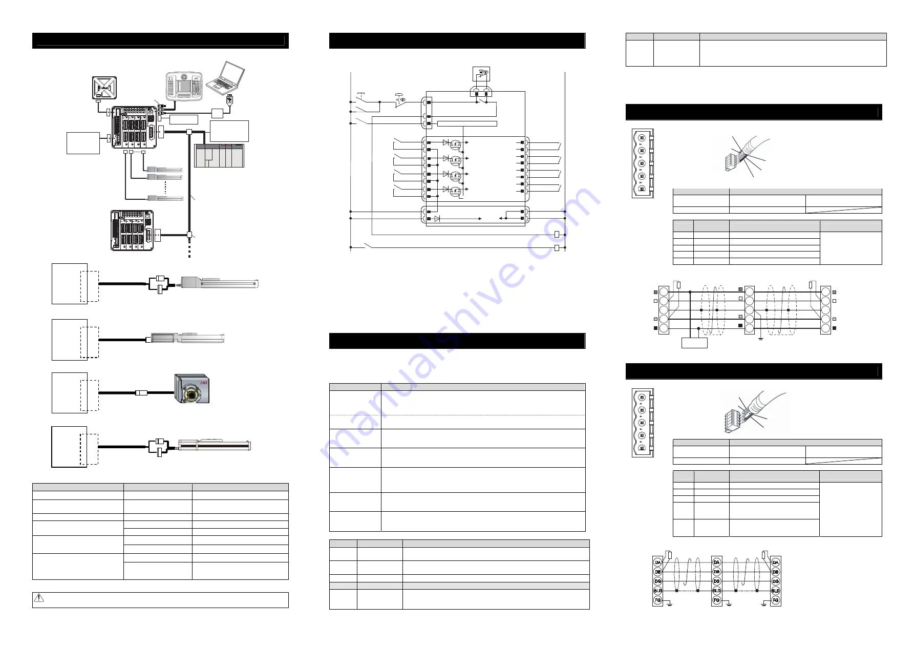
Wiring
1) Connection to RCP2 Series
2) Connection to RCP6, RCP5, RCP4, RCP3, RCA2 RCD and RCL Series
3) Connection to RCP2 Small Rotary Series
4) Connection to RCA Series
Note 1 Connection Cable Model Codes
□□□
: Cable length Example) 030 = 3m
Model
Cable Model
Remarks
RCP2 other than rotary small type
CB-PSEP-MPA□□□
Robot cable from 0.5 to 20m
RCP2 rotary small type
(RTBS/RTCS/RTBSL/RTCSL)
CB-RPSEP-MPA□□□
Robot cable from 0.5 to 20m
RCA
CB-ASEP2-MPA□□□
Robot cable from 0.5 to 20m
CB-APSEP-MPA□□□
Robot cable from 0.5 to 20m
RCP3, RCA2, RCL
CB-APSEP-MPA□□□-LC
Standard cable from 0.5 to 20m
CB-CA-MPA□□□-RB
Robot cable from 0.5 to 20m
(Note 3)
RCP4 (Other than SA3/RA3),
RCD-RA1DA(-D3)
(Note 2)
CB-CA-MPA□□□
Standard cable from 0.5 to 20m
(Note 3)
CB-CAN-MPA□□□-RB
Robot cable from 0.5 to 20m
(Note 3)
RCP6, RCP5, RCP4(SA3/RA3),
RCD-RA1DA(-D5)
(Note 2)
/ GRSNA
Gripper/Rotary of RCP2CR,
RCP2W
CB-CAN-MPA□□□
Standard cable from 0.5 to 20m
(Note 3)
Note 2
-D3/-D5 in brackets ( ) for RCD show the symbols for the applicable controllers.
Note 3 The maximum cable length for RCD is 10m for both the standard cable and robot cable.
Caution: Follow the content described in the model code record card inserted to the controller when connecting.
Wrong connection will issue an error such as the encoder wire breakage.
Power Supply and Emergency Stop Circuit
The following diagram shows an example of how the emergency stop switch for the teaching pendant may
be included in the emergency stop circuit you may construct.
EMGINSLOT0
EMGINSLOT1
EMGINSLOT2
EMGINSLOT3
Emergency Stop
Reset Switch
Emergency Stop
Switch
CR1
SIO Connector
CR1
24V
0V
Emergency Stop Control Circuit
Motor Power Supply (Slot 3)
(Axis No.6 and 7)
MPISLOT3
MPOSLOT3
CR2
(Note 2)
MPISLOT2
MPOSLOT2
CR2
(Note 2)
MPOSLOT1
MPISLOT1
CR2
(Note 2)
MPISLOT0
MPOSLOT0
CR2
(Note 2)
Motor Power Supply (Slot 2)
(Axis No.4 and 5)
Motor Power Supply (Slot 1)
(Axis No.2 and 3)
Motor Power Supply (Slot 0)
(Axis No.0 and 1)
MP+24V
0V
V
0
V
4
2
+
P
C
Control
Power
External Drive Cutoff •
Emergency Stop Input Connector
Power Line Input Connector
EMG+SLOT0
(Note 5)
S1
4
3
2
1
12
11
10
9
7
8
5
6
15
16
13
14
1
3
4
2
Emergency Stop Switch on
Teaching Pendant
S2
(Note1)
EMG A
EMG B
MCON
8
5
EMG-
EMG+SLOT1
(Note 5)
EMG+SLOT2
(Note 5)
EMG+SLOT3
(Note 5)
3
2
4
CR1
(Note 4)
CR2
(Note 2)
CR1
System I/O Connector
Operation Mode Selected (Other than Motion Network)
(Note) SSCNET
Ⅲ
/H type, MECHATROLINK-III type and EtherCAT Motion type of Motion Network is not
applicable for the operation modes listed below.
This controller possesses 7 types of operation mode to select from as the fieldbus specification.
The settings are to be established with Gateway Parameter Setting Tool.
● Operation Patterns of Fieldbus Specification
Operation Mode
Contents
Simple Direct Mode
The target position can be indicated directly by inputting a value. Also, monitoring of the
current position is available in 0.01mm unit.
Those other than the target position are to be indicated in the position table, and the setting
can be done for 256 points at maximum.
Positioner 1 Mode
The 256 points of position data can be registered at the maximum and is able to stop at the
registered positions. Also, monitoring of the current position is available in 0.01mm unit.
Direct Indication Mode
The target position, speed acceleration/deceleration and pressing current limit can be
indicated with inputting a number. Monitoring of not only the current position, but also the
current speed and indicated current are available.
Positioner 2 Mode
This is the operation mode of the position data of 256 points at maximum set in the position
table. The monitoring of the current position is not available.
This mode is that the transferred data is reduced from Positioner 1 Mode.
Positioner 3 Mode
This is the operation mode of the position data of 256 points at maximum set in the position
table. The monitoring of the current position is not available
This is the mode to control with the minimized number of signals to perform the positioning
operation by reducing the amount of sent and received data from Positioner 2 Mode.
Positioner 5 Mode
This is the operation mode of the position data of 16 points at maximum set in the position table.
It is a mode that enabled to monitor the current position in 0.1mm unit by reducing the
number of position table from Positioner 2 Mode.
Remote I/O Mode
It is the operation mode to control with ON/OFF of bits like PIO (24V input and output).
Control with five patterns, PIO Pattern 0, 1, 2, 4 and 5, is available. (Refer to Remote I/O
Operation Patterns below.)
● Remote I/O Operation Patterns (PIO patterns are to be switched over in driver board parameter No.25.)
PIO Pattern Operation Mode
I/O Type
0
Positioning
Mode
Number of positions 64 points
Zone signal output 1 point
(Note 1)
Position zone signal output
(Note 2)
1 point
1
Teaching Mode Number of positions 64 points
Position
zone signal output
(Note 2)
1 point
JOG operation available
Writing of current position to indicated position available
2
256points Mode Number of positions 256 points
Position
zone signal output
(Note 2)
1 point
3
-
Cannot be used. Make any setting will cause parameter error.
4
Electromagnetic
Mode 1
Number of positions 7 points
Zone signal output 1 point
(Note 1)
Position
zone signal output
(Note 2)
1 point
Operation indication available only by indicating position number
PIO Pattern Operation Mode
I/O Type
5
Electromagneti
c Mode 2
Number of positions 64 points
Zone signal output 1 point
(Note 1)
Position
zone signal output
(Note 2)
1 point
Operation with moving forward / moving backward / intermediate position indications
Signal output equivalent to limit switch available for complete signal
Note 1: Set the range of the zone in parameter. It becomes constantly valid once the home-return operation
is complete.
Note 2: The range of the zone is to be set in the position table, and is activated only when that position
number is indicated. It is invalid in other position number commands. The position zone signal can
be switched over to the zone signal with the setting of Parameter No.149.
DeviceNet
Type
Refer to the instruction manuals for each fieldbus master unit and mounted PLC for the details.
Connector Name
DeviceNet Connector
Cable Side
MSTB2.5/5-STF-5.08 AU M
Enclosed in standard package
Manufactured by PHOENIX CONTACT
Controller Side
MSTB2.5/5-GF-5.08 AU
Pin No.
Signal Name
(Color)
Description
Applicable cable diameter
1
V- (BK)
Power Supply Cable Negative Side
2
CAN L (BL)
Communication Data Low Side
3
Shield (None)
Shield
4
CAN H (WT)
Communication Data High Side
5
V+ (RD)
Power Supply Cable Positive Side
Dedicated cable for
DeviceNet
Slave Devices
MCON-DeviceNet Type
V+
Drain
(Shield)
CAN_H
CAN_L
V-
RD
WT
BL
BK
RD
WT
BL
BK
V+
Drain
(Shield)
CAN_H
CAN_L
Grounding resistance at 100
Ω
or less
(Class D grounding)
V+
Drain
(Shield)
CAN_H
CAN_L
V-
RD
WT
BL
BK
Communication power needs to be
supplied by an external device.
Terminal Resistance is required
to be mounted on the terminal.
V-
Terminal Resistance
121
Ω
Master Unit
Terminal Resistance
121
Ω
24V
Power Supply
CC-Link Type
Refer to the instruction manuals for each fieldbus master unit and mounted PLC for the details.
Connector Name
CC-Link Connector
Cable Side
MSTB2.5/5-STF-5.08 AU
Enclosed in standard package
Manufactured by PHOENIX CONTACT
Controller Side
MSTB2.5/5-GF-5.08 AU
Pin No.
Signal Name
(Color)
Description
Applicable cable diameter
1
DA (BL)
Communication Line A
2
DB (WT)
Communication Line B
3
DG (YW)
Digital GND
4
SLD
Connect the shield of the shielded cable
(Connect the FG of the 5 pins and
controller FG internally)
5
FG
Frame Ground
(Connect the SLD of the 4 pins and
controller FG internally)
Dedicated cable for CC-Link
MCON
AX0 to 7
Actuator
Connector
MCON
AX0 to 7
Actuator
Connector
MCON
AX0 to 7
Actuator
Connector
MCON
AX0 to 7
Actuator
Connector
Connection Cable
(Note 1)
Connection Cable
(Note 1)
Connection Cable
(Note 1)
Connection Cable
(Note 1)
1
2
3
4
5
Front View of
Connector on
Controller side
Shield
BL (CAN L)
RD (V+)
WT (CAN H)
BK (V-)
1
2
3
4
5
Front View of
Connector on
Controller side
WT (DB)
BL (DA)
Shield (SLD)
YW (DG)
Note 1 MCON-C: When there is nothing plugged in the SIO connector, S1 and S2 are short-circuited inside
the controller.
MCON-CG: When there is nothing plugged in the SIO connector, S1 and S2 are not short-circuited
inside the controller.
When the short-circuited, the enclosed dummy plug DP-5 plugged in the SIO connector.
Note 2 When the motor driving source is cut off externally for a compliance with the safety category, relay a
contact such as a contactor to the wires between MPISLOT
and MPOSLOT
.
Note 3 The rating for the emergency stop signal (EMG-) to turn ON/OFF at contact CR1 is 24V DC and 10mA.
Note 4 For CR1, select the one with coil current 0.1A or less.
Note 5 By cutting out the connection between EMG+SLOT
and EMGINSLOT
, only the disconnected slot
number can be made in the condition of an emergency stop. (
: Slot Number)
(Note) If supplying power with using a 24V DC, having it turned ON/OFF, keep the 0V connected and have the
+24V supplied/cut (cut one side only).
Slave Devices
MCON-
CC-Link
Type
SLD and FG are internally connected.
Terminal Resistance is required
to be mounted on the terminal.
The terminal resistor differs depending on the type
of the dedicated cable for CC-Link.
• Cable FANC-SBH···130
Ω
1/2W
(High Performance Cable
dedicated for CC-Link)
• Cable FANC-SB······110
Ω
1/2W
(CC-Link Dedicated Cable)
Master Unit
Terminal
Resistance
Terminal
Resistance
Grounding resistance at 100
Ω
or less
(Class D grounding)
Teaching Pendant
Touch Panel Teaching
(to be purchased separately)
Host System (Master Unit)
(PLC, etc.…Please prepare separately)
Communication power
supply (if necessary)
(24V DC
…Please prepare
separately)
Actuator
Emergency Stop
Circuit
Control/Drive Power
Supply
(24V DC
…Please prepare
separately)
PC software
(to be purchased separately)
Absolute Battery Box
Each Fieldbus
communication cable
Follow the specifications of
each Fieldbus for how to
lay out wiring.
For MCON-CG,
in case a teaching
tool is not connected
to SIO connector,
have the enclosed
dummy plug (DP-5)
plugged in the connector.