


27
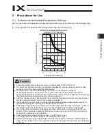
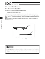
5. Precautions for Use
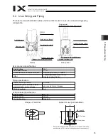
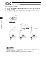
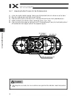
User connector pins and corresponding Y-terminals
z
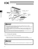
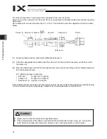
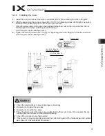
Before commencing wiring/piping work, turn off the power to the controller and the power/air
supplies to the robot. Failure to do so may cause the robot to malfunction.
z
Use cables and tubes within their specifications. Failure to do so may result in fire or short circuit
due to an overheated cable, or may cause air leaks.
z
Connect the shielded cable to pin 16. Failure to do so may cause the robot to malfunction due to
noise.
To base
Inside unit
Cable
Arm 2 side
Connection
D-sub, 15-pin
Indicator
(LED)
Controller side
Y-terminal designation
Wire color
Orange 1 red
Light gray 1 red
Connection
Y-terminal
Orange 1 black
Light gray 1 black
White 1 red
White 1 black
Yellow 1 red
Yellow 1 black
Pink 1 red
Pink 1 black
Orange 2 red
Orange 2 black
White 2 red
White 2 black
Yellow 2 red
Green
Light gray 2 red
Light gray 2 black
No.
1
2
3
4
5
6
7
8
9
10
11
12
13
14
15
16
U1
U2
U3
U4
U5
U6
U7
U8
U9
U10
U11
U12
U13
U14
U15
LED +24V
LED G24V
FG
ALM
User Connecto
r
Warning
Содержание Intelligent Actuator IX Series
Страница 2: ......
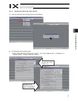
Страница 51: ...45 6 Inspection Maintenance 8 Click the OK button 9 Click the Encoder Rotation Data Reset2 button ...
Страница 55: ...49 6 Inspection Maintenance 6 Click the Servo OFF button 7 Press the emergency stop switch ...
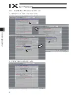
Страница 57: ...51 6 Inspection Maintenance 9 Click the OK button 10 Click the Encoder Rotation Data Reset2 button ...
Страница 75: ......