


I/O Signals
Function description for I/O Signals
Category
Signal
Abbreviation
Signal Name
Function Description
CSTR
PTP strobe signal
(start signal)
The actuator will start to move to the position set by
the command position number.
PC1 to PC256
Command position
number signal
Input of the position number to move (binary input)
BKRL
Forced brake
release signal
The brake will forcibly be released.
RMOD
Operating mode
selector signal
The operating mode is selectable when the MODE
switch of the controller is set to AUTO. (The operating
mode of the controller will become AUTO when this
signal is turned OFF, or MANU when this signal is
turned ON.)
*STP
Pause signal
When this signal turns OFF while the actuator is
moving, the actuator will decelerate to stop. The
remaining movement is retained and will resume when
the signal is turned ON again.
RES
Reset signal
An alarm will be reset when this signal is turned ON.
The remaining movement can be canceled when the
pause signal is OFF (STP is OFF).
SON
Servo ON signal
The servo remains ON while this signal is ON, or OFF
while this signal is OFF.
HOME
Home return signal
The controller will perform home return operation when
this signal is turned ON.
MODE
Teaching mode
signal
The operating mode will change to the teaching mode
when this signal is turned ON. (At this time, the mode
will not be selected unless all signals of CSTR, JOG+
and JOG- are OFF and the actuator operation has
stopped.)
JISL
Jog/inching selector
signal
The actuator will jog with JOG+ or JOG- when this
signal is OFF. It will inch with JOG+ or JOG- when this
signal is ON.
JOG +, JOG - Jog signal
When the JISL signal is OFF, the actuator will jog
toward the +/- direction upon detection of an OFF
→
ON
rise edge of this signal.
If an ON
→
OFF fall edge of this signal is detected while
the actuator is jogging, the actuator will decelerate to a
stop.
PWRT
Teaching signal
When the write position is specified in the teaching
mode and this signal has remained ON for 20msec or
longer, the controller will write the current position in
the specified position field.
Input
ST0 to ST6
Start position
command
In the electromagnetic valve mode, the actuator will
move to the specified position when this signal is ON.
(The start signal is not required.)
PEND/INP
Positioning
completion signal
This signal will turn ON when the target position has
been reached after movement and the actuator has
entered the in-position range. The PEND signal will not
turn OFF but the INP signal will turn OFF if the position
deviation exceeds the in-position range. PEND or INP
can be selected by the parameter.
PM1 to PM256
Completed position
number signal
The relevant position number will be output when
positioning has been completed (binary output).
HEND
Home return
completion signal
This signal will turn ON when home return has been
completed.
ZONE1
Zone signal
This signal will turn ON when the current actuator
position enters the range set by the parameters.
PZONE
Position zone signal
This signal will turn ON when the current actuator
position enters the range specified in the position data
after position movement. The combined use with
ZONE 1 is possible, but PZONE becomes effective
only for movement to the set position.
RMDS
Operating mode
status signal
The operating mode status will be output.
*ALM
Controller alarm
status signal
This signal remains ON in normal conditions of use
and turns OFF when an alarm is generated.
MOVE
Moving signal
This signal will remain ON while the actuator is moving
(including home return and push & hold times).
SV
Servo ON status
signal
This signal will remain ON while the servo is ON.
*EMGS
Emergency stop
status signal
This signal remains ON while the controller is under
the emergency stop reset condition and turns OFF
when the emergency stop condition is enabled.
MODES
Mode status signal
This signal will turn ON when the teaching mode is
enabled by the input of the mode signal and will turn
OFF when the mode changes to the normal mode.
WEND
Write completion
signal
This signal will turn OFF after the controller has
switched to the teaching mode. It will turn ON when
writing in response to the PWRT signal has been
completed. When the PWRT signal turns OFF, this
signal will also turn OFF.
PE0 to PE6
Current position
number signal
In the electromagnetic valve mode, this signal will turn
ON when the actuator completes moving to the target
position.
LS0 to LS2
Limit switch output
signal
This signal will turn ON when the current actuator
position enters the positioning band of the target
position. It will be output even before the movement
command if home return has been completed.
LOAD
Load output
judgment status
This signal will be output when the load exceeds the
current value set as the “threshold” within the range of
zone+ and zone- in the position data during push &
hold operation. It is used to judge whether pressing
has been performed normally.
Output
TRQS
Torque level status
signal
This signal will be output when the slider (rod) collides
against an obstacle during push & hold operation and
the motor current value reaches the value set as the
“threshold” in the position data.
I/O Signals
Parameter (PIO) Pattern Selection
0
1
2
3
4
5
Positioning
mode
Teaching
mode
256-point
mode
512-point
mode
Electromagnetic
valve mode 1
Electromagnetic
valve mode 2
Number of
positioning points
64 points
64 points
256 points
512 points
7 points
3 points
Zone signal
○
*
*
*
○
○
Pin
No.
Category
Position zone
signal
○
○
○
*
○
○
1A
24V
P24
2A
24V
P24
3A
MC
4A
MC
5A
IN0
PC1
PC1
PC1
PC1
ST0
ST0
6A
IN1
PC2
PC2
PC2
PC2
ST1
ST1 (JOG+)
7A
IN2
PC4
PC4
PC4
PC4
ST2
ST2
8A
IN3
PC8
PC8
PC8
PC8
ST3
9A
IN4
PC16
PC16
PC16
PC16
ST4
10A
IN5
PC32
PC32
PC32
PC32
ST5
11A
IN6
MODE
PC64
PC64
ST6
12A
IN7
JISL
PC128
PC128
13A
IN8
JOG+
PC256
14A
IN9
BKRL
JOG-
BKRL
BKRL
BKRL
BKRL
15A
IN10
RMOD
RMOD
RMOD
RMOD
RMOD
RMOD
16A
IN11
HOME
HOME
HOME
HOME
HOME
17A
IN12
*STP
*STP
*STP
*STP
*STP
18A
IN13
CSTR
CSTR/PWRT
CSTR
CSTR
19A
IN14
RES
RES
RES
RES
RES
RES
20A
Input
IN15
SON
SON
SON
SON
SON
SON
1B
OUT0
PM1
PM1
PM1
PM1
PE0
LS0
2B
OUT1
PM2
PM2
PM2
PM2
PE1
LS1 (TRQS)
3B
OUT2
PM4
PM4
PM4
PM4
PE2
LS2 (-)
4B
OUT3
PM8
PM8
PM8
PM8
PE3
5B
OUT4
PM16
PM16
PM16
PM16
PE4
6B
OUT5
PM32
PM32
PM32
PM32
PE5
7B
OUT6
MOVE
MOVE
PM64
PM64
PE6
8B
OUT7
ZONE1
MODES
PM128
PM128
ZONE1
ZONE1
9B
OUT8
PZONE
PZONE
PZONE
PM256
PZONE
PZONE
10B
OUT9
RMDS
RMDS
RMDS
RMDS
RMDS
RMDS
11B
OUT10
HEND
HEND
HEND
HEND
HEND
HEND
12B
OUT11
PEND
PEND/WEND
PEND
PEND
PEND
13B
OUT12
SV
SV
SV
SV
SV
SV
14B
OUT13
*EMGS
*EMGS
*EMGS
*EMGS
*EMGS
*EMGS
15B
OUT14
*ALM
*ALM
*ALM
*ALM
*ALM
*ALM
16B
Output
OUT15
LOAD/TRQS *1
LOAD/TRQS *1 LOAD/TRQS *1 LOAD/TRQS *1
17B
NC
18B
NC
19B
0V
N
20B
0V
N
(NOTE) The terms inside parentheses indicate functions before home return.
*1: Signal for PCON-CF only
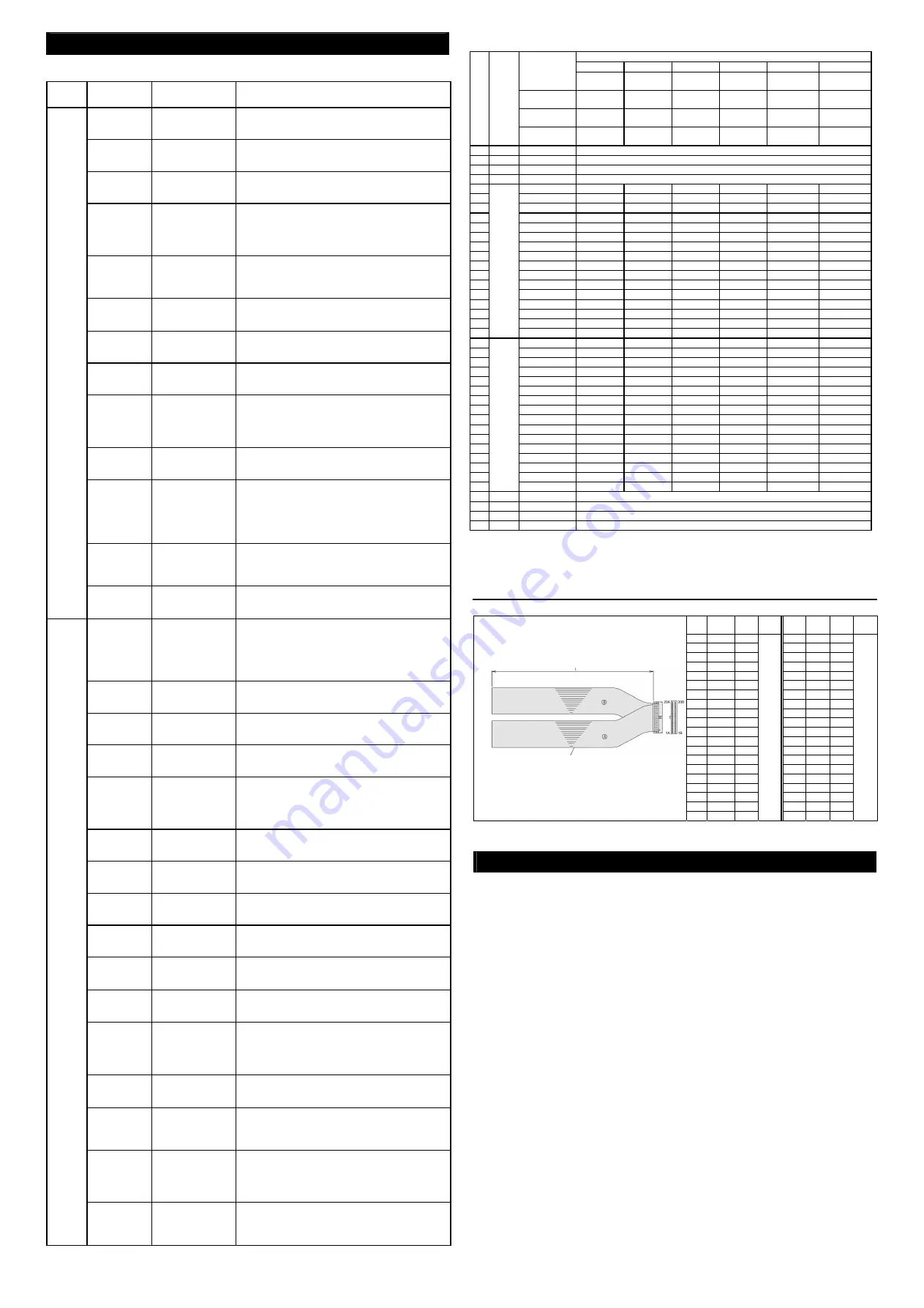
I/O Flat Cable
Model:
CB-PAC-PIO
* Enter the cable l
ength (L) in
(up to 10m)
Example) 080 = 8m
HIF6-40D-1.27R
No.
Signal
Name
Cable
Color
Wiring
No.
Signal
Name
Cable
Color
Wiring
1A
24W
BR-1
1B
OUT0 BR-3
2A
24W
RD-1
2B
OUT1 RD-3
3A
OR-1
3B
OUT2 OR-3
4A
YW-1
4B
OUT3 YW-3
5A
IN0
GN-1
5B
OUT4 GN-3
6A
IN1
BL-1
6B
OUT5 BL-3
7A
IN2
PL-1
7B
OUT6 PL-3
8A
IN3
GY-1
8B
OUT7 GY-3
9A
IN4
WT-1
9B
OUT8 WT-3
10A
IN5
BK-1
10B OUT9 BK-3
11A
IN6
BR-2
11B OUT10 BR-4
12A
IN7
RD-2
12B OUT11 RD-4
13A
IN8
OR-2
13B OUT12 OR-4
14A
IN9
YW-2
14B OUT13 YW-4
15A
IN10
GN-2
15B OUT14 GN-4
16A
IN11
BL-2
16B OUT15 BL-4
17A
IN12
PL-2
17B
PL-4
18A
IN13
GY-2
18B
GY-4
19A
IN14
WT-2
19B
0V
WT-4
20A
IN15
BK-2
Fla
t
ca
b
le
(A
)
(P
re
ss
w
e
ld
in
g
)
20B
0V
BK-4
Fl
at cabl
e (
B
) (
P
re
ss w
e
ld
ing)
AW
G
28
BR: Brown, RD: Red, OR: Orange, YW: Yellow, GN: Green, BL: Blue, PL: Purple, GY: Gray, WT: White, BK: Black
Starting Procedures
When using this product for the first time, pursue work while making sure to avoid omission
and incorrect wiring by referring to the procedure below.
1.
Check of Packed Items
Check packed items with the packing list. Should there be any incorrect model or
insufficient item, contact your dealer.
2.
Installation
Install the controller and actuator.
3.
Wiring
Connect the 24V DC power supply, earth cable, emergency stop circuit, motor drive
power supply, motor cable, encoder cable and I/O flat cable.
4.
Power Supply and Alarm Check
(1) Connect the PC or teaching pendant and set the mode selector switch to the
MANU side.
(2) After confirming that the emergency stop circuit is not activated, supply the input
power.
- When the controller functions properly:
The monitor LED [SV/ALM] illuminates for 2 seconds and then goes out.
- When an alarm generates:
The monitor LED [SV/ALM] illuminates in red.
After checking the contents of the alarm using the PC or teaching pendant,
remove the cause.
Flat calve (20 conductors) x 2
Half pitch MlL
socket
HIF6-40D-1.27R
(HIROSE)
Open-
end
ed
Open-
end
ed


