i
6
OIM AI-5X82 V2.1 Page 6 of 6
338, New Sonal Link Service Industrial Premises Co-op Society Ltd,
Building No.2, Link Road, Malad (W), Mumbai - 400064.
Tel: 022-66939916/17/18;
E-mail : [email protected]
Website : www.itherm.co.in
Mfgd by: Innovative Instruments & Controls LLP
i
USER GUIDE :
1)
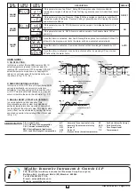
ON-OFF ACTION :
In this mode, output (Relay/SSR) remains ON, till
actual temperature reaches to the set point. On
reaching SP, output turns OFF & remains OFF, till
actual temperature drops down (in heat logic) or
raises (in cool logic) equal to hysterisis set by user.
(As shown in Fig : 3.1 & 3.2)
TEMP (°C)
SP
AMB
O/P
ON
ON
ON
OFF
OFF
TIME
HEAT LOGIC / ON-OFF
Fig: 3.1
HYSTERISIS
TEMP (°C)
SP
AMB
O/P
O/P
ON
ON
ON
OFF
OFF
TIME
HYSTERISIS
COOL LOGIC / ON-OFF
Fig: 3.2
2) TIME PROPORTIONAL ACTION :
In this mode, ON & OFF time of Output (Relay/SSR)
varies proportionally in every cycle (cycle time
settable by User) depending on the deviation of PV
w.r.t SP. This action starts/continues only, when PV
enters or is within the band. (As shown in Fig : 3.3)
TIME
TEMP (°C)
SP
AMB
Fig: 3.3
ON
100%
ON
100%
OFF
100%
OUTPUT
TIME PROPORTIONAL ACTION
ACTIVE ZONE
PROPORTIONAL BAND (P.BAND)
SET BY USER
3) MANUAL RESET (OFFSET ADJUSTMENT) :
In some applications, after adopting Time
Proportionating action, system may stabilize at
particular temperature over a period of time which
can be different than the set value. This steady state
(error) offset can be eliminated by setting this value,
equal and opposite to the existing offset. (As shown
in Fig : 3.4)
TEMP (°C)
SP
AMB
TIME
Fig: 3.4
OFFSET
After offset adjustment
ALARM
LOGIC
If this parameter is set as ‘Direct’, Relay/SSR energizes under Alarm condition &
remains de-energized otherwise. ‘Direct’ setting is generally used for Audio/Visual alarm
output.
If this parameter is set as ‘Reverse’, Relay/SSR de-energizes under Alarm condition &
remains energized otherwise. ‘Reverse’ setting is generally used for tripping the process
under alarm conditions.
ALARM
INHIBIT
If this parameter is set to ‘YES’ & Alarm condition persists, it will disable Alarm O/P at
power ON.
If this parameter is set to ‘NO’ & Alarm condition persists, it will enable Alarm O/P at
power up.
DIRECT
NO
ALARM
ACK.
Once the Alarm is activated, User has following three options to de-activate it. When PV
falls within the programmed limits, the alarm will be de-activated automatically.
Once the alarm is activated, it remains activated until acknowledged manually by UP
key.
Once the alarm is activated, it can be de-activated either by pressing UP key or when
PV falls within the alarm limits.
AUTO
PARA
METER
LOWER
DISPLAY
UPPER
DISPLAY
DESCRIPTION
DEFAULT
NC
: Normally Close terminal of relay
NO
: Normally Open terminal of relay
OP1
: Output 1
OP2
: Output 2
PV
: Process Value (Actual temperature)
C.A.: Control Action
CJC: Cold Junction Compensation
CM : Common terminal of relay
EMI : Electro Magnetic Interference
LWC: Lead Wire (Length) Compensation
SP
: Set Point Value (Set temp.)
SSR
: Solid State Relay
T.P.
: Time Proportional
T/C
: Thermocouple
ABBREVIATION


