background image


11 - DOCUMENTAZIONE ALLEGATA 

11-1


11 - 2 


11.1 

LIST OF ENCLOSURES 

ELECTRICAL DIAGRAMS 


Содержание Tritotutto 50

Страница 1: ...TTO ISVE MANUALE D USO E MANUTENZIONE TRITURATORE MODELLO 80 80D I S V E S r l Via San Martino 39 25020 Borgo Poncarale Bs Italy tel 030 2540351 fax 030 2640874 Internet www isve com E Mail headoffice isve com ...

Страница 2: ...DRESS Via San Martino 39 425020 Poncarale Bs Italia Tel 39 030 2540351 Fax 39 030 2640874 e mail headoffice isve com http www isve com DOCUMENT CODE TRITOTUTTO5080D I 2003 EDITION 00 01 2003 PRODUCT SHREDDER MODEL 5080D COMPLIANCE ...

Страница 3: ...3 3 1 GENERAL NORMS 3 2 3 2 USES ENVISAGED NOT ENVISAGED AND INCORRECT 3 4 3 2 1 Envisaged use 3 4 3 2 2 Non envisaged use 3 4 3 3 SAFETY DEVICES 3 5 3 4 SAFETY DEVICES INSTALLED ON THE MACHINE 3 5 3 5 ACOUSTIC CHARACTERISTICS GENERATED NOISE LEVEL 3 7 3 6 IDENTIFICATION AND CERTIFICATION PLATES 3 8 3 7 DRIVE AND CONTROL ZONES AND DANGEROUS ZONES 3 9 3 8 RESIDUAL DANGERS AND RISKS 3 10 3 9 1 Resid...

Страница 4: ...RATIONS 6 2 6 2 PROGRAMMING MACHINE PARAMETERS WITH MINIDISP01 VI CARD ON OPERATOR PANEL 6 3 7 1 MAINTENANCE 7 2 7 2 WEEKLY CHECKS 7 3 7 3 SIX MONTHLY CHECKS 7 3 7 4 YEARLY CHECKS 7 4 7 5 DISMANTLING CUTTER GROUP 7 4 7 6 DISMANTLING GRID 7 7 7 7 ASSEMBLING GRID 7 7 8 1 FAULTS CAUSES AND REMEDIES 8 2 8 2 ELECTRICAL FAULTS 8 4 9 1 DISCONTINUE USING 9 2 9 1 1 Demolition of the machine 9 2 9 2 WASTE D...

Страница 5: ...0 CONSULTATION OF THE MANUAL 0 1 I 0 1 INDEX 0 1 INTRODUCTION 2 0 2 CONSERVATION OF THE MANUAL 2 0 3 SEARCH CRITERIA AND CONSULTATION OF THE MANUAL 3 0 4 WHO THE MANUAL IS INTENDED FOR 4 ...

Страница 6: ...s the right to make those construction and commercial changes it feels necessary to improve the product at any time without engaging to rapidly update this publication I S V E reserves all the rights to reproduce this manual 0 2 CONSERVATION OF THE MANUAL The manual is an integral part of the machine and must always accompany it even should it be sold This manual must be kept in a place easy to ac...

Страница 7: ... 1 1 1 1 Possible further sub title This manual also contains some optional groups which can be used with the machine on request from the customer therefore the description on some parts may not coincide with your machine The page numbers of each chapter start from zero so there is the prefix indicating the chapter and the number in progression staring from 1 at the beginning of each chapter To ma...

Страница 8: ...he machine function in normal conditions to calibrate the mechanical units to carry out maintenance and necessary repairs NOT QUALIFIED TO CARRY OUT WORK ON ELECTRICAL UNITS WHILE STILL POWERED Operator service electrician Qualified technician able to drive and make the machine function in normal conditions he can deal with all the electrical calibration maintenance and repair work HE IS QUALIFIED...

Страница 9: ...1 GENERAL INFORMATION 1 1 I 1 1 INDEX 1 1 GUARANTEE 2 1 2 REFERENCES TO NORMATIVES 3 1 3 APPLICABLE DIRECTIVES 3 ...

Страница 10: ...e covered by the guarantee occur to the machine during the period of validity the company following specific checks will arrange for repairs or substitution of the detective parts following forwarding of the parts in question to the manufacturer I S V E holds itself responsible for the machine in its original configuration Any change to the configuration or functioning of the machine must be carri...

Страница 11: ...ocumentation UNI 7543 Safety colours and safety signs EN 60204 1 Safety of machinery Electrical equipment of machines Part 1 general regulations CEI 44 5 EN 60947 3 Low voltage equipment Part 3 Switches disconnectors switch disconnectors and fuse combination units CEI 17 11 EN 12012 1 Rubber and plastics machines Size reduction machines Part 1 Safety Requirements for blade granulators 1 3 APPLICAB...

Страница 12: ...OF THE MACHINE AND TECHNICAL CHARACTERISTICS 2 1 I 2 1 INDEX 2 1 DESCRIPTION OF THE MACHINE 2 2 2 TECHNICAL CHARACTERISTICS 3 2 3 OVERALL DIMENSIONS 3 2 4 PERMISSIBLE ENVERONMENTAL CONDITIONS 5 2 5 OPERATING SPACE 5 ...

Страница 13: ...ged disks 3 provided with hooks 2 Each hook has the task of hooking on to the product and to transport it towards the cutters 4 assembled on two or more counter rotating driving shafts which slice the material Drive unit asynchronous AC electric motor linked to an epicycloidal gearmotor connected between the cutter holder shafts and transporters with oil bath lubrication for the gears Safety devic...

Страница 14: ...2 DESCRIPTION OF THE MACHINE AND TECHNICAL CHARACTERISTICS 2 1 I 2 3 2 3 OVERALL SIZE ...

Страница 15: ...ust in suspension bacterial loads insects and anything else which may be hazardous for the product or the operators is totally forbidden For optimal functioning of the machine we recommend an environment with a temperature of between 5 and 40 C 2 5 OPERATING SPACE The machine should be positioned so as to allow sufficient free space around the machine respecting the measurements given in the drawi...

Страница 16: ...se 4 3 3 SAFETY DEVICES 5 3 4 SAFETY DEVICES INSTALLED ON THE MACHINE 5 3 5 ACOUSTIC CHARACTERISTICS NOISE LEVEL GENERATED 7 3 6 IDENTIFICATION AND CERTIFICATION PLAQUE 8 3 7 COMMAND AND CONTROL ZONES AND DANGEROUS AREAS 9 3 8 RESIDUAL RISKS AND DANGERS 11 3 8 1 Residual cutting risk 10 3 8 2 Residual risk generated by noise 10 3 8 3 Residual risk generated by rotor blocking 10 ...

Страница 17: ...tuation he finds himself in The person in charge of the machine or responsible for maintenance should pay careful attention to the type of clothes worn for example avoid using clothes which can easily get hitched to parts of the machine avoid wearing a tie or have clothing which flaps avoid wearing large rings or bracelets which could become entangled in the machinery Before starting to use the ma...

Страница 18: ...D ACCIDENT PREVENTION 3 1 I 3 3 NOTE The definition qualified personnel are those who have attended special training courses etc and have experience as regards to installing starting up and maintenance of machines ...

Страница 19: ... or in order to achieve results outside those prescribed is to be considered NON CONTEMPLATED USE and therefore INCORRECT WARNING The machine must not be used to work inflammable explosive toxic noxious or ferrous materials or materials which during working become so The machine has not been designed to operate in environments where the atmosphere is explosive therefore installation in such enviro...

Страница 20: ...nly be removed by using specific equipment and will not remain in position unless anchored using the supporting elements WARNING Always make sure the guards are assembled before starting the machine Emergency stop Stop push buttons The emergency stop STOP push button is located on the Control Panel Ref 5 Fig 03 00 red mushroom key on yellow background This push button is to be used each there is a...

Страница 21: ... normal cleaning operations stop the machine and disconnect the power to the switchboard IMPORTANT Before removing the block on the front opening it is important to make sure that the emergency push buttons are deactivated To reset close the front panels and reactivate the knob Opening shredder inspection door safety switch if present On the left right of the shredder hopper there is a door which ...

Страница 22: ...tors by Society of the Plastic Industry UNI 7712 Tool machines Noise measurement in the work place 1977 UNI EN ISO 3746 Acoustics Determination of sound power level of noise sources using sound pressure Survey method using an enveloping measurement surface over a reflecting plane 1997 Measuring was carried out sing a BRUEL KJAER type 2236 sound level meter Measurements were taken only from positio...

Страница 23: ...TION AND CERTIFICATION PLATE The figure shows the identification plate on the machine The model serial number and year constructed stamped on the plate must be used each time a request for information is made regarding the machine or when ordering spare parts ...

Страница 24: ...DENT PREVENTION 3 1 I 3 9 3 7 COMMAND AND CONTROL ZONES AND DANGEROUS ZONES 1 Command zone switchboard 2 Work area loading material 3 Work area unloading material 4 Dangerous internal area of the machine cutting chamber ...

Страница 25: ...s generally within the acoustic pressure safety limits However given the different types of material should the noise exceed threshold allowed we advise the use of acoustic protection cabins or headsets Important The clothes to be worn and the means of protection must comply with the CEE 686 directives as regards to personal protection or as an alternative according to the regulations in force in ...

Страница 26: ...4 ISTRUZIONI PER L INSTALLAZIONE 4 1 I 4 1 INDEX 4 1 HANDLING REGULATIONS 2 4 2 TRANSPORT 6 4 3 LIFTING 6 4 4 INSTALLATION 6 ...

Страница 27: ...is flat and is able to carry the weight of the machine in the area set aside for the machine there is sufficient room for handling the products to be worked and maintenance operations can be carried out without difficulty 4 2 TRANSPORT The machine is usually forwarded on a pallet and protected by a cellophane covering On arrival we advise you to check to make sure the machine has not been damaged ...

Страница 28: ...ut the handling operations 4 4 INSTALLATION IMPORTANT Make sure that the base the machine will rest on is compact solid and perfectly flat so that it can support the machine rigidly without any vibrations The flooring we recommend is reinforced concrete with smooth support surface POSITION THE MACHINE IN AN AREA WHICH IS LARGE ENOUGH SO THAT THE OPERATOR HAS THE NECESSARY SPACE TO CARRY OUT MAINTE...

Страница 29: ...MAND AND CONTROL EQUIPMENT 2 5 1 1 Control console 2 5 2 ELECTRICAL CONNECTIONS 3 5 3 PRE START CHECKS 4 5 3 1 Check without turning 4 5 4 OPERATING MODES 4 5 5 STOP AND EMERGENCY MODES 4 5 5 1 Stop work cycle 4 5 5 2 Emergency stop 5 5 5 3 Power cut stop 5 ...

Страница 30: ...ch lockable when in position 0 so that work can be carried out on the machine in complete safety 5 EMERGENCY STOP push button By pressing this push button it is possible to stop the machine operating immediately including any optional groups connected to it in the case of an emergency 6 START UNIT push button By pressing this push button the shredder begins to function 7 STOP UNIT push button By p...

Страница 31: ... machine to the electric mains using clamps R S T T placed inside the base of the switchboard WHEN ORDERED IF DIFFERENT VOLTAGES ARE NOT SPECIFIED THE MACHINE IS ALWAYS DELIVERED WITH V380 AND HZ50 5 3 PRE START CHECKS NOTE Have this operation carried out by a qualified electrician maintenance operator IMPORTANT Before starting the machine it is advisable to check 6to maker sure that during transp...

Страница 32: ...e machines subject of this document are designed to function only in the automatic mode After enabling all the groups required for the production cycle the machine only needs to be fed with material which can be either manual with the help of the operator or automatic by means of special loading devices 5 5 STOP AND EMERGENCY MODES 5 5 1 Stop work cycle See paragraph 6 1 5 5 2 Emergency stop Emerg...

Страница 33: ... This type of stop must be used only justifiable cases of emergency NOTE To re arm the emergency push button the red mushroom must be pulled outwards 5 5 3 Stop due to power cut Should there be a power cut BLACK OUT the operating cycle stops immediately which could cause a block of the cutter group caused by material still present in the cutting chamber To restore the work conditions restart the m...

Страница 34: ...6 FUNCTIONING 6 1 I 6 1 INDEX 6 1 STARTING UP AND OPERATING OPERATIONS 6 2 PROGRAMMING MACHINE PARAMETERS WITH MINIDISP01 VI BOARD OPERATOR PANEL 2 ...

Страница 35: ...into the hopper 5 at the end of the work press push button 7 Off and wait until the cycle finishes 6 In case of emergency press the EMERGENCY STOP push button NOTE load a different programme select a number from 1 9 and confirm by pressing the Enter key START SHREDDING USING START STOP PUSH BUTTONS 1 Power using the main switch 2 press push button 6 START to start the shredder and feed the materia...

Страница 36: ...omatic switch off Programming write in the time in minutes using the numerical key confirm by pressing enter note an 0 setting means it will always remain on Time shredder ON will appear on the display Description should the pause work function of the shredder be envisaged this parameter indicates the operating time of the crusher Programming insert the time you wish the shredder to remain on an 0...

Страница 37: ...P will appear on the display if bin is present Description if you want the bin to rise gradually to avoid all the material being tipped into the shredder chamber the thrust of the pneumatic piston can be adjusted by setting an operating and a pause time Programming insert the length of time seconds you want the bin to be raised using the numerical key confirm by pressing enter Time bin stopped wil...

Страница 38: ...hredder remains stopped when it has to invert direction 20 2 0 seconds t start up shredder 4 x100 ms The length of time in hundreds of milliseconds the controller does not check the current of the shredder motor to avoid false inversions 15 1 5 seconds t start up mill 5 x100 ms The length of time in hundreds of milliseconds the controller does not check the current of the mill to avoid false inver...

Страница 39: ...n the mill is actuated following the parameter 15 length of time to allow removal of any residual material 5 Time sensors 17 ms The time expressed in milliseconds within which the current sensors must signal continuous overload before any blocking actions are carried out so as to avoid brief overloads causing false inversions 15 T belt if error 18 sec This is the time in seconds within which the b...

Страница 40: ...7 MAINTENANCE I 7 1 INDEX 7 1 MAINTENANCE 2 7 2 WEEKLY CHECKS 3 7 3 SIX MONTHLY CHECKS 3 7 4 ANNUAL CHECKS 4 7 5 DISMANTLING CUTTER GROUP 4 7 6 DISMANTLING SCREEN 7 7 7 ASSEMBLING SCREEN 7 ...

Страница 41: ...lectric mains supply When the electrical equipment is powered certain parts of this equipment could be dangerous Behaviour not complying with the safety instructions for the use of this equipment could result in injury to persons and damage to things Scrupulously keep to the instructions in the paragraphs regarding each maintenance operation After carrying out the maintenance operations and before...

Страница 42: ...RD ON THE SIDE OPPOSITE THE MOTORS CHECK TO MAKE SURE THAT THE BOLTS HOLDING THE BUSHINGS ON THE CUTTER SHAFTS AND FEEDERS ARE TIGHT CHECK LUBRICATION OF THE BEARINGS CHECK TO MAKE SURE THE HOLES OF THE SCREEN ARE NOT CLOGGED 7 3 SIX MONTHLY CHECKS CHECK OIL IN GEARBOX B TYPE IP MELLANA 680 CHECK OIL IN GEARMOTOR A TYPE IP MELLANA 320 CUTTERS CHECK SHARPNESS ...

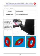
Страница 43: ... BEARINGS AND SEALS SHREDDER BLADES SHARPENING Using an abrasive disk with 60 grain or a professional sharpening system you must pass green surfaces only those clearer Do not work on red zones darker parts as the tool thickness will reduce and this would compromise its functionality ...

Страница 44: ...al protection guard PHASE 3 Once the protection panel has been removed the shaft anchoring units can be accessed PHASE 4 Remove the anchoring bolts of the shaft terminals PHASE 5 Once the bolts have been unscrewed remove the blocking bushings PHASE 6 Remove all the bushings the shaft terminals must be free for the following dismantling phases ...

Страница 45: ...I 7 MAINTENANCE 7 6 PHASE 7 Remove the two lateral pins PHASE 8 Remove all the plate anchoring bolts PHASE 9 Tighten the two extractor dowels to free the plate ...

Страница 46: ...e operation the shredder group can be accessed Slide out the cutters and feeder disks making sure to position them in the sequence they were removed It is important when re assembling that each component occupies the same position as before in the shredding chamber ...

Страница 47: ... screen B Force the pins out by tugging on them If the screen does not drop insert a piece of wood from the top of the hopper between the cutters so that it can come into contact with the screen Using a hammer knock the piece of wood alternating the knocks on the two opposite sides WARNING The screen weighs roughly 50kg Make sure the area in which the screen drops is free The weight of the item co...

Страница 48: ...8 LOOKING FOR FAULTS 8 1 I 8 1 INDEX 8 1 FAULTS CAUSES AND SOLUTIONS 2 8 2 ELECTRICAL FAULTS 4 ...

Страница 49: ...al in the cutting chamber Screens assembled incorrectly Check the sharpening method of the cutters Contact the supplier Check the rotation direction of the rotor Look for the cause with the operator Check the assembly procedure Excessive wear of cutters Incorrect position of the cutters Abrasive material Re establish the assembly direction of the cutters and tighten the screws of the head bushings...

Страница 50: ... or partial clogging of the screen holes Cutters worn or burnt Cutters too close together Screen holes too small Reduce feed of material to be shredded Remove the screen and clean the holes Replace with new cutters Check the distance between the cutters Increase the diameter of the screen holes Tab 8 1 B ...

Страница 51: ...rent A thermal switch on the motor has triggered Overload block The safety switch is broken Cutting chamber too full Check fuses Press the button of the motor thermal switch inside the switchboard If the fault repeats it may depend on the fact that the relay is calibrated too low In this case turn the black disk placed on the aforesaid relay anticlockwise using a screwdriver making sure not to exc...

Страница 52: ...9 WASTE DISPOSAL DEMOLITION 9 1 I 9 1 INDEX 9 1 DISCONTINUE TO USE 2 9 1 1 Demolition of the machine 2 9 2 WASTE DISPOSAL 2 ...

Страница 53: ...llows Disconnect the machine from the electric mains Remove the electric cables exiting from the selector switch Remove the electric power cables from the switchboard WARNING Should the area around the machine be wet dry it before going on any further Remove the cutters Remove the main parts of the machine Separate the parts of the machine into their different categories e g plastic materials meta...

Страница 54: ...10 LIST OF SPARE PARTS 10 1 I 10 1 INDEX 10 1 RULES FOR ORDERING SPARE PARTS 2 ...

Страница 55: ...arts order from I S V E s r l Via San Martino 39 25020 Poncarale Bs Italy Tel 0039 030 2540351 Fax 0039 030 62640874 Remember to quote from the shredder plate 1 Type of shredder 2 Serial number from the spare parts table 1 Table number 2 Reference number 3 Code number 4 Number required ...

Страница 56: ...11 DOCUMENTS ENCLOSED 11 1 I 11 1 INDEX 11 1 LIST OF ENCLOSURES 2 ...

Страница 57: ...I 11 DOCUMENTAZIONE ALLEGATA 11 1 11 2 11 1 LIST OF ENCLOSURES ELECTRICAL DIAGRAMS ...

Отзывы: