

CABLINE-VSF CONN. Instruction Manual
Document No.
HIM-13010
3
/
12
Confidential C
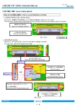
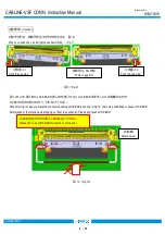
【コネクタ挿入手順
/ Connector Mating Method
】
1
.
FPC
側コネクタのセット方法(
Direction to mate.
)
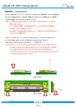
図
3
のように、基板側コネクタの基準
pin
に
FPC
側コネクタの基準
pin
がくるように、セットします。
As shown in Fig.3, please set plug so that the datum pin mark of the plug connector and the receptacle connector are matched.
図
3
(
Fig.3
)
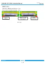
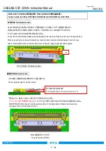
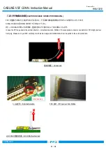
2
.嵌合方法
(How to mate.)
図
4
のように、
FPC
を水平に押し、ロック穴にロックが掛かると、嵌合完了となります。
As shown in Fig.4, push FPC horizontally until it is locked.
図
4
(
Fig.4
)
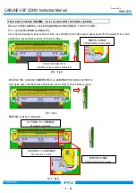
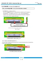
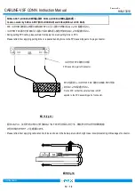
SHELL (LOCK BAR
無し
)
の場合
/ For the connector SHELL(Without LOCK BAR).
FPC
を水平に挿入する
Insert FPC to the connector horizontally.
⇒
FPC
側コネクタ基準
pin
Datum pin of plug connector.
Plug shell
と
Rece shell
がオーバーラップ
している事を確認
Check the overlap of Plug shell and Rece shell.
ロックが掛かっている事を確認
Check if it is locked.
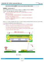
基板側コネクタ基準
pin
Datum pin of receptacle connector.
I-PEX MARK
Rece shell
Plug shell
ロックが掛かっている事を確認
Check if it is locked.
隙間がないか確認
Confirm whether there is space.