

CABLINE-VSF CONN. Instruction Manual
Document No.
HIM-13010
12
/
12
Confidential C
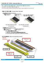
SHELL ASS’Y(LOCK BAR
有り品
)
及び
SHELL(LOCK BAR
無し品
)
共通
/
Common matter by SHELL ASS’Y(With LOCK BAR) and SHELL(Without LOCK BAR).
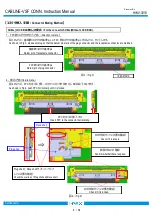
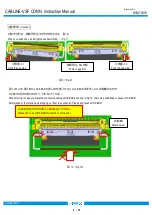
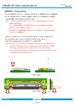
・
FPC
コネクタの取り回しの際には特定の
FPC
に引っ張り力が集中しないように配慮ください。
・コネクタの
FPC
取り付け部に引っ張り力及び繰り返し変位が加わらないように配慮ください。
・
During setting FPC cable, please refrain from apply too much pulling force to FPC.
・
Please refrain from applying pulling force or repeated bending force to the FPC assembly part of a plug connector.
図
15 (Fig.15)
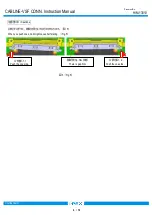
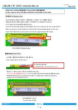
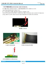
・
図
16
のように、矢印方向に常に力が加わるような
FPC
の引き回しを行うと、嵌合外れやコネクタの破損等
の恐れがありますので、ご注意願います。
・
Please refrain from applying cable retention force as shown in the below picture which might case incomplete mating or breakage of connector.
図
16(Fig.16)
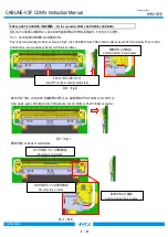
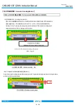
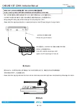
FPC
を固定し、コネクタの
FPC
取り付け部に外力が加
わらないように配慮ください。
Fix the FPC so that the external force is NOT
applied to the FPC assembly part of connector.
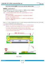
コネクタの
FPC
取り付け部
FPC assembly part of Connector.


