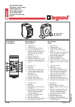
4.2 BUILT-IN CURRENT TRANSFORMER
The mGARD-100 has a built-in current sensor (ZSCS) with 2.0” (50.8 mm) opening. The maximum continuous
primary phase current is 250 Amps. Refer to Table 4.1 below to determine the cable sizes that will fit through the
internal ZSCS.
WIRE SIZE
14
12
10
8
6
4
2
Diameter (inches)
0.126
0.142
0.179
0.241
0.31
0.358
0.418
of Cable (mm)
3.2
3.6
4.6
6.1
7.9
9.1
10.6
Table 4.1 Number of Conductors through the window of the mGard-100
3 Cables in.
(form factor 2.16) mm
0.27
0.3
0.39
0.52
0.67
0.77
0.95
6.9
7.8
10
13
17
20
23
4 Cables in.
(form factor 2.42) mm
0.3
0.34
0.43
0.59
0.75
0.87
1.02
7.74
8.7
11
15
19
22
26
6/7 Cables in.
(form factor 3.0) mm
0.37
0.43
0.54
0.73
0.93
1.07
1.26
9.6
10.8
14
18
24
27
32
9/10 Cablse in.
(form factor 3.85) mm
0.49
0.55
0.69
0.93
1.19
1.38
1.62
12.3
13.9
18
24
30
35
41
12 Cables in.
(form factor 4.15) mm
0.52
0.59
0.75
1
1.29
1.47
1.74
13.3
14.9
19
25
33
38
44
Sensor Type Inside
Diameter in mm
mGARD-100
T3A
T6A
2.0
2.75
5.75
50
70
146
no. of cables in feeder
Figure 4.0 illustrates a wiring arrangement for detecting ground faults on a solidly grounded system. Pass the
neutral and phase conductors through the ZSCS window. Note that the relay is located downstream of the neutral
ground point.
Figure 3.0 mGARD-SYM Remote Indicator


