S706/5
EXTERNAL SWITCH CONNECTION
5. Connect up to three pairs of remote passive switch contacts, rated to a
minimum of 5V AC/DC 1 Amp, to the corresponding input connections
terminals (see connections diagram) using suitable signal cable with a
maximum length of 100 metres.
INPUT ACTIVATION AND CONFIGURATION
6. Connect the remote passive switch contacts to the input connections
terminals inside the RWD box as per connections diagram.
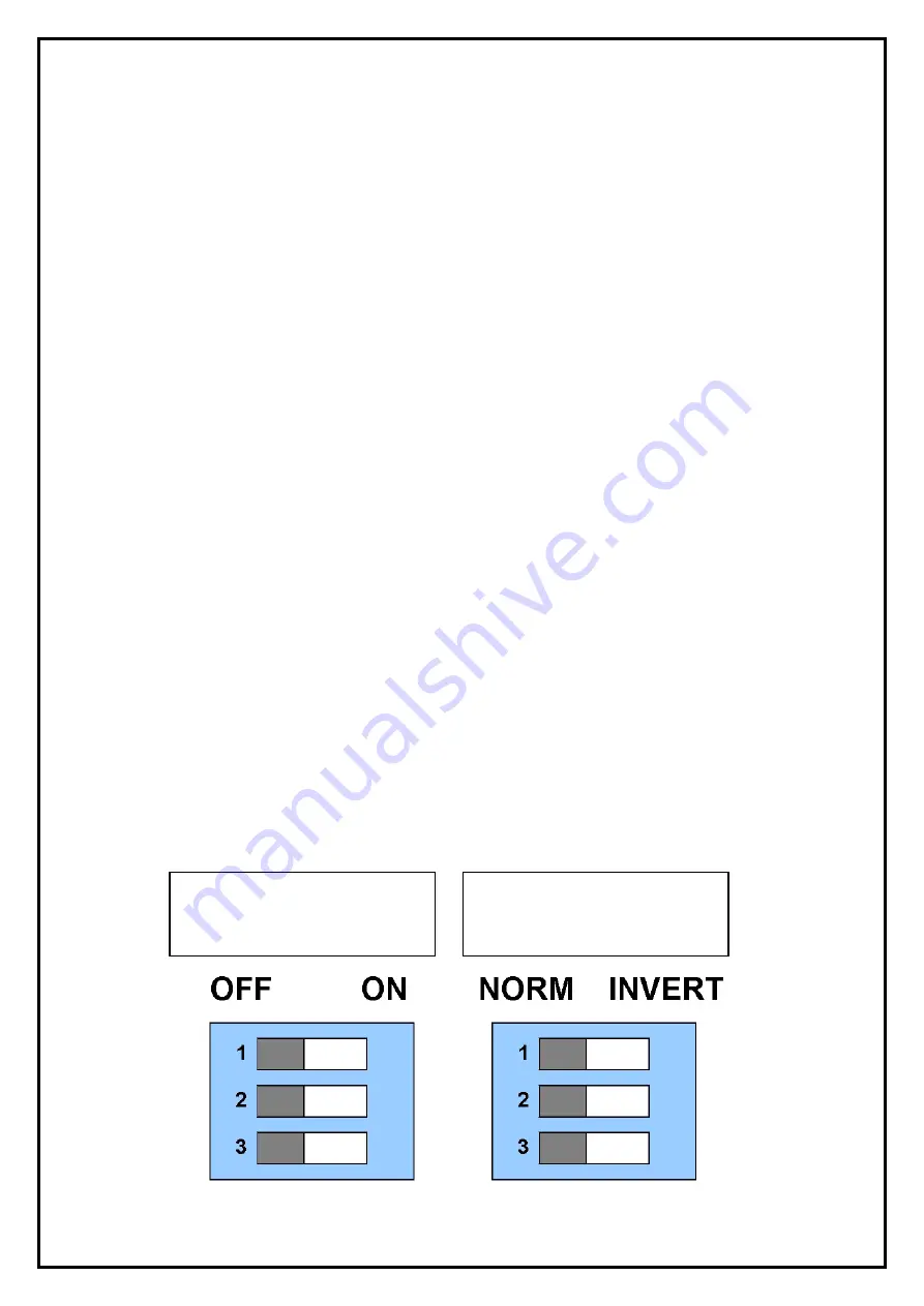
7. After connecting the desired amount of pairs of switch contacts, activate
the corresponding channels by setting the appropriate channel activation
dipswitch to "ON" position. See Dip switch settings diagram.
NB: If a channel activation dipswitch is in the "OFF" position and a
switch connected to the corresponding terminals is operated, the
RWD alarm will not function.
8. Set the switch setting dipswitches to the appropriate position (NORM =
normally open, INVERT = normally closed) to enable the RWD to alarm
when the remote switch is activated. See Dip switch settings diagram.
DIPSWITCH SETTINGS DIAGRAM
SWITCH
SETTING
CHANNEL
ACTIVATION
Содержание RWD
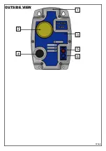
Страница 7: ...S706 5 2 4 5 6 1 3 OUTSIDE VIEW ...

