TC-600 Service Manual
13
DET
FM IF IC1
IF AMP
HPF
AMP
IC7
AF
LPF
HPF
DET
2
39 40
1
SW
Q12
SW
AF/PF AMP
IC7
LPF
IC11
MCU
B
U
S
Y
M
U
T
E
A
F
C
O
T
I
IC8
SP
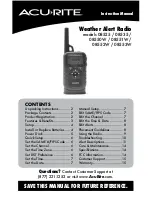
Figure 3
Audio Amplifier and Squelch Circuit
6) Receive Signaling
CTCSS/CDCSS
Over 300Hz audio frequencies of the signal output from IF chip is cut off by a low pass filter. The
resulting signal enters the microprocessor IC11. IC11 determines whether the CTCSS/CDCSS
matches the preset value, and controls the MUTE, AFCO and the speaker output according to the
squelch results.
2-Tone
The output 2-Tone signal from IF chip goes to IC7 (1/4) for voltage amplification, then is processed by
shaping circuit that is comprised of IC7 (2/4) and other components before being detected by IC11
Pin11. IC11 determines whether the 2-Tone matches the preset value, and controls MUTE, APCO and
speaker output according to squelch results.
3. PLL Frequency Synthesizer
PLL circuit generates the first local oscillator signal for reception and the RF signal for transmission.
1) PLL
The step frequency of PLL circuit is 5KHz\6.25KHz\12.5 KHz\
10
KHz. A 12.8MHz reference
oscillator signal is divided at IC2 by a fixed counter to produce a 5 KHz\6.25KHz\12.5 KHz\
10
KHz reference frequency. The output signal from voltage control oscillator (VCO) passes
through buffer amplifier Q14 and is divided at IC2 by the programmable dual-module counter.
The divided signal is compared in the phase comparator IC2 with the 5 KHz\6.25KHz\12.5
KHz\25 KHz reference signal. The output signal from phase comparator is filtered by a