

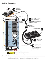
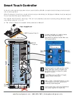

HyNet Gateway
Pin 1, COM
Installer supplied
shielded cable
STOP BUTTON
OPEN BUTTON
CLOSE BUTTON
REMOTE OPEN AND
RADIO CONTROL
OPEN/CLOSE
1
OPEN PARTIAL
INTERLOCK OPEN
TIME CLOCK OPEN
FREE EXIT DETECTOR
DISABLE EXIT DETECTOR
DISABLE CLOSE TIMER
INSIDE OBSTRUCTION
VEHICLE DETECTOR
OUTSIDE OBSTRUCTION
VEHICLE DETECTOR
SHADOW/RESET
VEHICLE DETECTOR
SENSOR 1
SENSOR COM
DO NOT USE
DO NOT USE
DO NOT USE
CHARGER
AC LOSS
LOCK INTERLOCK
EMERG CLOSE
FIRE DEPT OPEN
2
3
4
5
6
7
8
9
10
11
12
14
15
16
17
18
19
20
21
22
23
24
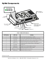
Smart Touch Controller
LIMIT
DUAL GATE
RADIO OPTIONS
DRIVE
POWER
RS485
MO
TOR
USER 1
USER 2
USER 3
VEHICLE DETE
CT
OR
VEHICLE DETE
CT
OR
VEHICLE DETE
CT
OR
ST
OP
/B
UZZER
FREE
EXIT
INSIDE
OBS
TR
OUT
SIDE
OBS
TR
SHADO
W
RE
SET
WI
EGAND
Hy
Security
COM
NO
MX000585
VERSION
S/N
RS232
DISPLA
Y
VEHICLE DETE
CT
OR
COM
COM
A
B
RPM
COM
OPEN
S 1
+24V
+24V
STATUS
LED
24V A
C Ac
cessor
y pow
er
+ 24
V D
C
COM
MO
N
+ 24VDC
Inputs
SENSOR 2
SENSOR 3
Pin 1, +24V
DO NOT connect to +24V tabs at base of
Smart Touch Controller. Only use the +24V
connections on the Power Supply Board.
CAUTION
NOTE:
More detailed wiring information
is shipped with the HyNet.
+24VDC Accessory Power (+)
Drawing is not to scale.
Attach shielded cable
to wire harness.*
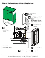
2
1
Attach to RS-485
port on HyNet.
3
Connect to RS-485 port on
Smart Touch Controller.
4
Connect flying
lead to +24VDC.
Tact
button
Wire harness
(supplied in box)
5
Supply RJ-45 network
connection
HyNet
RS-485
port
Smart Touch Controller
RS-485
Connector
Common Bus (-)
RS-485 Connector
RS-485 ports
Power Supply Board
*Measure distance between
HyNet and Controller
connections for appropriate
shielded cable length.
www.SecureOpeners.com | (800) 878-7829 | [email protected]


