ELECTRICAL SYSTEM 7-4
●
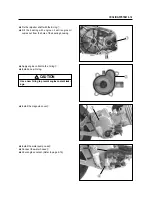
Turn the ignition switch to the “ ” (ON) position.
●
Grasp the front or rear brake lever.
●
Press the starter switch and allow the engine to
crank for a few seconds, and then measure the
ignition coil primary peak voltage.
●
Repeat the above procedure a few times and
measure the highest ignition coil primary peak
voltage.
If the peak voltage is lower than the specified values,
inspect the ignition coil. (Refer to below)
▣
▣
IGNITION COIL RESISTANCE INSPEC-
TION
●
Lift and support the side cover with the side cover
stay. (Refer to page 2-2)
●
Disconnect the ignition coil read wire.
Measure the ignition coil resistance in bolt the prima-
ry and secondary windings. If the resistance is not
within the standard range, replace the ignition coil
with a new one.
WARNING
While testing, do not touch the tester probes and
spark plug to prevent receiving an electric shock.
Tester knob indication : Voltage ( )
150 V and more
Ignition coil primary peak voltage
Tester knob indication : Resistance (
ΪΪ
)
Pocket tester : 09900-25002
IGNITION COIL / PLUG CAP RESISTANCE
3.5 ~ 5.5
Ϊ
(
�
Terminal -
�
Terminal)
20 ~ 31
㏀
(Plug cap -
�
Terminal)
Secondary
Primary
▣
▣
PICK-UP COIL RESISTANCE INSPECTION
●
Lift and support the side cover with the side cover
stay. (Refer to page 2-2)
●
Disconnect the pick-up coil lead wire coupler.
Measure the resistance between the lead wires and
ground. If the resistance is not specified value, the
pick-up coil must be replaced.
Tester knob indication : Resistance (
ΪΪ
)
Pocket tester : 09900-25002
Pick-up coil
resistance
80 ~ 120
ΪΪ
( Green - Blue )
∞
ΪΪ
( Green - Ground )
Содержание MS3 125
Страница 6: ...NOTE Difference between photographs and actual motorcycles depends on the markets ...
Страница 46: ...3 3 ENGINE Remove the exhaust pipe nuts Remove the water hoses and Remove the muffler mounting bolts ...
Страница 105: ...FI SYSTEM DIAGNOSIS 4 8 IAP sensor WT sensor TO sensor SAV solenoid Pick up coil Oxygen sensor ECU 10 12 11 8 9 10 ...
Страница 134: ...5 1 FUEL SYSTEM AND THROTTLE BODY FUEL SYSTEM ...
Страница 139: ...FUEL SYSTEM AND THROTTLE BODY 5 6 THROTTLE BODY ...
Страница 211: ...CHASSIS 8 32 REAR WHEEL REMOVAL Remove the muffler connecting bolt Remove the muffler mounting bolts Remove the muffler ...
Страница 249: ...9 31 SERVICING INFORMATION WIRE AND CABLE ROUTING ...
Страница 250: ...SERVICING INFORMATION 9 32 ...
Страница 251: ...9 33 SERVICING INFORMATION ...
Страница 252: ...SERVICING INFORMATION 9 34 ...
Страница 253: ...9 35 SERVICING INFORMATION WIRING DIAGRAM ...
Страница 254: ...SERVICING INFORMATION 9 36 ...
Страница 257: ...Prepared by 1st Ed DEC 2007 Manual No 99000HP8810 Printed in Korea ...


