FI SYSTEM DIAGNOSIS 4-14
SELF-DIAGNOSTIC PROCEDURES
Don’t disconnect couplers from ECU, battery cable
from battery, ECU ground wire harness from engine
or main fuse before confirming malfunction code
(self-diagnostic trouble code) stored in memory.
Such disconnection will erase memorized information
in ECU memory.
Malfunction code stored in ECU memory can be
checked by the special tool.
To check malfunction code, read SELF-DIAGNOSIS
FUNCTION “DEALER MODE” (Refer to page
4-10,11) carefully to have good understanding as to
what functions are available and how to use it.
Be sure to read “PRECAUTIONS for Electrical Circuit
Service” (Refer to page 4-1) before inspection and
observe what is written there.
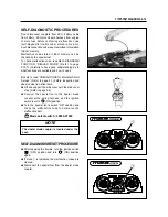
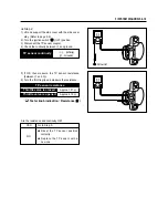
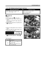
●
Lift and support the side cover with the side cover
stay. (Refer to page 2-2)
●
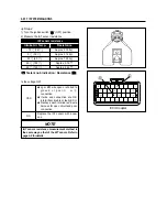
Connect the special tool to the dealer mode
coupler at the wiring harness, and the ignition
switch is set to “ ” (ON) position.
●
Turn the special tool’s switch “ON” position and
check the malfunction code to determine the
malfunction part.
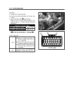
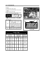
SELF-DIAGNOSIS RESET PROCEDURE
●
After repairing the trouble, turn the ignition switch
“ ” (OFF) position and turn “ ” (ON) position
again.
●
If clock
①
is indicates, the malfunction codes are
cleared.
●
Disconnect the special tool from the dealer mode
coupler.
NOTE
The dealer mode coupler is located under the
seat.
Mode select switch : 09900-27000
①
①
Содержание MS3 125
Страница 6: ...NOTE Difference between photographs and actual motorcycles depends on the markets ...
Страница 46: ...3 3 ENGINE Remove the exhaust pipe nuts Remove the water hoses and Remove the muffler mounting bolts ...
Страница 105: ...FI SYSTEM DIAGNOSIS 4 8 IAP sensor WT sensor TO sensor SAV solenoid Pick up coil Oxygen sensor ECU 10 12 11 8 9 10 ...
Страница 134: ...5 1 FUEL SYSTEM AND THROTTLE BODY FUEL SYSTEM ...
Страница 139: ...FUEL SYSTEM AND THROTTLE BODY 5 6 THROTTLE BODY ...
Страница 211: ...CHASSIS 8 32 REAR WHEEL REMOVAL Remove the muffler connecting bolt Remove the muffler mounting bolts Remove the muffler ...
Страница 249: ...9 31 SERVICING INFORMATION WIRE AND CABLE ROUTING ...
Страница 250: ...SERVICING INFORMATION 9 32 ...
Страница 251: ...9 33 SERVICING INFORMATION ...
Страница 252: ...SERVICING INFORMATION 9 34 ...
Страница 253: ...9 35 SERVICING INFORMATION WIRING DIAGRAM ...
Страница 254: ...SERVICING INFORMATION 9 36 ...
Страница 257: ...Prepared by 1st Ed DEC 2007 Manual No 99000HP8810 Printed in Korea ...


