50
HYDROCLEAR PUREWATER SYSTEM (con nued)
UV
-
C LAMP REPLACEMENT INSTRUCTIONS
Important:
It is mandatory that the UV
-
C lamp is replaced every 12 months to maintain op mum performance.
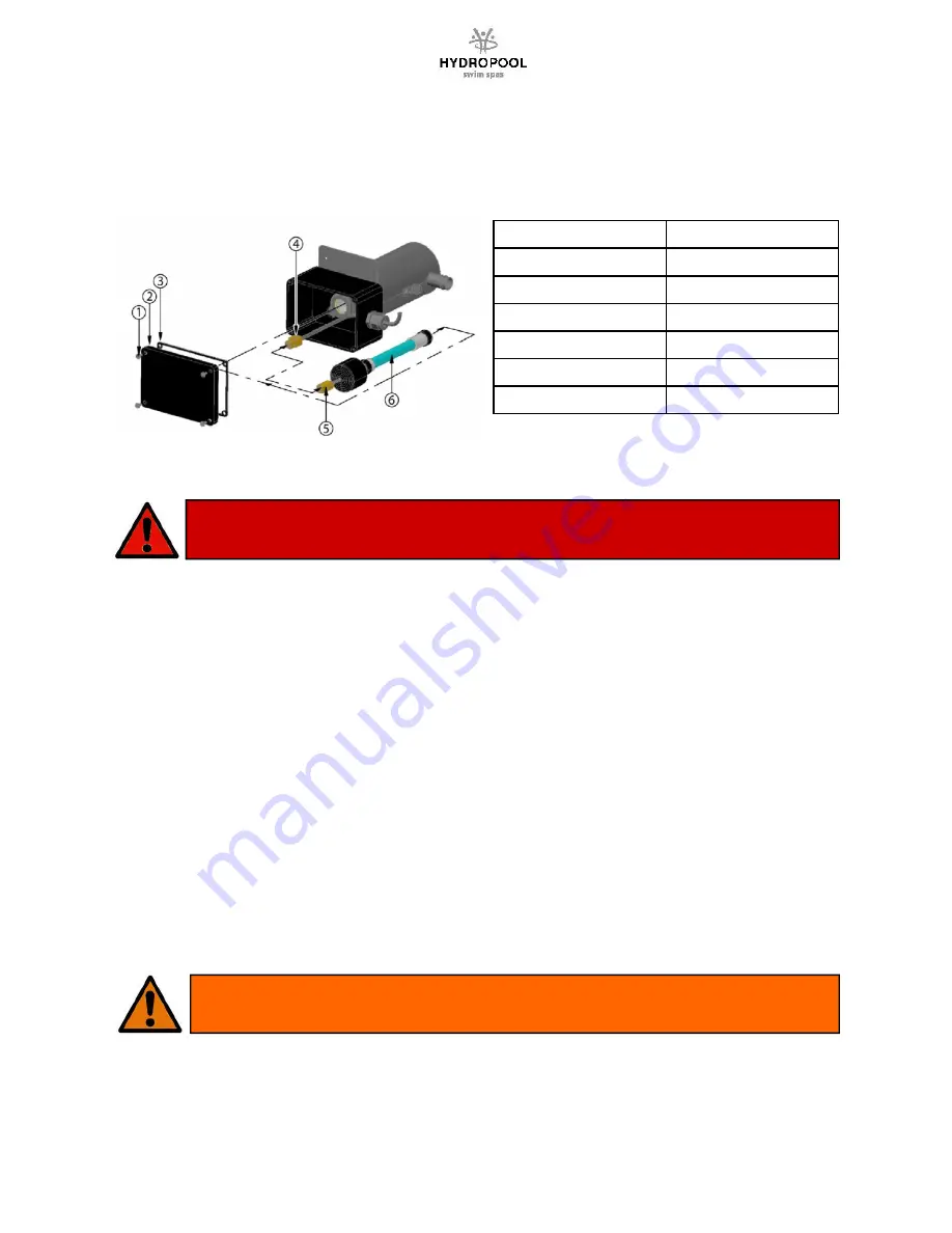
KEY
DESCRIPTION
1
SCREW
2
ENCLOSURE COVER
3
ENCLOSURE GASKET
4
BALLAST CONNECTOR
5
UV
-
C LAMP CONNECTOR
6
UV
-
C LAMP
NOTE: Your UV System unit may look different than shown in the picture
DANGER
·
Turn the spa breaker to the OFF posi on.
·
Allow the UV
-
C lamp (6) to cool down prior to removing it from the UV system.
·
Never look at the lit UV
-
C lamp (6). This can cause severe eye damage or blindness.
INSTRUCTIONS:
1.
Remove the UV system enclosure cover (2) by removing 4 Phillips screws (1). Keep the gasket (3) together
with the enclosure cover (2) for later use.
2.
Make sure to use latex glove when handling the UV
-
C lamp (6).
3.
Slowly disconnect the old UV
-
C lamp connector (5) from the ballast connector (4).
4.
Slowly remove the old UV
-
C lamp (6) from the UV unit.
5.
Slide the new UV
-
C lamp (6) into the UV unit.
6.
Reconnect the new UV
-
C lamp connector (5) to the ballast connector (4). Make sure the connectors mate
completely. Do not force.
7.
Reinstall the enclosure cover (2) with the gasket (3) and secure with screws (1).
8.
Reconnect the unit to the spa controller and reinstall the spa controller’s cover.
9.
Turn on the power to the spa.
10.
Once power is ac vated you can check the ballast to see if the unit is func oning. A solid green light indicates
the unit is being provided power and should always be on. A solid red light indicates that the UV
-
C lamp is
ac vated.
WARNING
The UV
-
C lamp used in this unit contains mercury. Properly dispose of the old UV
-
C lamp in accordance with
disposal laws. See
www.lamprecycle.org
.
Содержание 13FFP Aquaplay
Страница 62: ...62 IN YE 3 EU WIRING DIAGRAM ...
Страница 63: ...63 IN YE 3 NA WIRING DIAGRAM ...
Страница 64: ...64 IN YE 5 EU WIRING DIAGRAM ...
Страница 65: ...65 IN YE 5 NA WIRING DIAGRAM ...


