


33
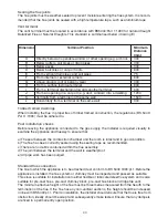
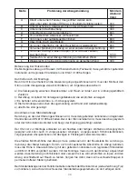
Dimension
Terminal Position
Minimum
Distance
(mm)
A
Directly below an openable window or other opening e.g. air brick
300
B
Below gutters, soil pipes or drain pipes
300
C Below
eaves
300
D
Below balconies or car port roofs
600
E
From vertical drain pipes and soil pipes
75
F
From internal or external corners
600
G
Above ground, roof or balcony level
300
H
From a surface facing a terminal
600
I
From a terminal discharging towards another terminal
600
J
From an opening in a car port (e.g. door, window) into a dwelling
1200
K
Vertically from a terminal on the same wall
1500
L
Horizontally from a terminal on the same wall
300
Timber framed dwellings
When installing the fl ue in properties of timber framed construction, the regulations (BS 5440:
Part 1:1990) must be adhered to.
Post installation checks
Before leaving the appliance connected to the gas supply, the installer is required visually to
examine the appliance and fl ueway to ensure that:
a) The seal between the combustion chamber and the room is intact and in good condition.
b) The fl ue has been correctly sealed using the sealing tape as recommended.
c) There are no debris contained within the fl ue assembly.
d) The joint between the terminal and the wall is weatherproof.
e) All pipe work has been purged
Standard fl ue connection
The fl ue to which the appliance is to be attached must conform to BS 5440 1990:pt.1. Before the
appliance is installed, the fl ue system or chimney must be inspected and passed as suitable.
This stove is suitable for installation onto either fl exible or fabricated steel fl ue system and is also
suitable for pre-cast fl ues, pre-cast chimney block, pre-cast fl ue block and ridge tile vent.
The minimum effective height of the fl ue must be three metres measured from the hearth to the
termination of the fl ue. If the fl ue has any non-vertical sections, the height should be increased
in line with BS 5440 pt.1. Prior to installation, the installer should ensure that the fl ue is free from
obstruction, ideally should be swept and subsequently smoke tested. Ensure that any dampers
are fi xed in a permanently open position.
Sealing the fl ue joints
The fl ue joints must be weather sealed to prevent moisture entering the fl ue system. It is recom-
mended that the fl ue joints be sealed with a high temperature tape, such as aluminium tape.
Vent terminal
The vent terminal must be located in accordance with BS5440:Part 1:1990 for natural draught
Balanced Flue or Natural Draughts. This standard is summarised below (drawing E)
Содержание Carmen gas
Страница 2: ...2...
Страница 4: ...4 650 A A 186 1077 869 462 532 A A 650 A A 182 850 686 442 528 A A Figaro gas Carmen gas A B...
Страница 6: ...6 G A E B C F F J H I D F K L G A H I D K F J a b E F...
Страница 7: ...7 G G1 G4 G5 G6 G7 G8 G9 G10 G11 G2 G3...
Страница 8: ...8 H H1 H2 H3 H4 H5...
Страница 50: ...50...
Страница 51: ...51...
Страница 52: ...52 DK 8362 H rning Tel 45 86 92 18 33 Fax 45 86 92 22 18 E mail heatdesign hwam com www hwamheatdesign com...