background image

19

18


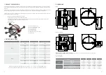
1

negative (direct-current) or neutral (alternating current)

2

positive (direct-current) or faze (alternating current)

S1

common micro switch closed damper

S2

normally closed micro switch closed damper

S3

normally open micro switch closed damper

S4

common micro switch open damper

S5

normally closed micro switch open damper

S6

normally open micro switch open damper

Tf1

temperature sensor on the outer side of the duct (ambienttemperature) max. 72°C

Tf2

temperature sensor on the inner side of the duct (temperature in the duct) max. 72°C

Tf3

temperature sensor on the inner side of the duct (temperature in the duct) max. 72°C

SCHISCHEK ExMax

Operation

Damper is delivered in closed position. When electric 

actuator  is  connected  to  the  power  supply  damper 

will open. When the damper reaches the end position 

(damper open), in which is it blocked, the electromotor 

will stop. Closing fire damper takes place automati¬-

cally  when  a  power  failure  occurs.  Thermal  tripping 

device that comes with fire damper causes power cir-

cuit break at a temperature of 72 °C (inside or outside 

duct). If checking is needed for proper functioning of 

fire damper, pushing the switch on the thermal tripping 

device will close damper. When switch on tripping de

-

vice is released, the damper will open.

Damper can be opened without connecting to a voltage with enclosed 

Allen key, by turning in the direction of the arrow on electric actuator 

(clockwise). After release of Allen key, damper will go to closed position. 

Type Examination Certificate Number: 

EXA 14 ATEX0064X

Equippment complies with the essential health and safety requirements 

relating to the design and construction of equippment intended to use 

in potentially explosive atmospheres given in annex II of the directive 

94/9/EC. 

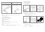
Wiring diagram

10. MAINTENANCE

- Observe the requirements specified in the NF S 61-933.

- Provide at least one annual check of the damper

- After each intervention, provide a systematic cleaning of dust and especially the solenoid and its movable plate

- Check the if the electrical terminals are tightened

9. EVOLUTION OR SERVICE KITS

  Designation

  Code

Fuse only mechanism

Fuse kit

FD-JHERM-72

Double contact S kit

FD-S-KIT

Upgr

adeabl

e t

o sol

enoid

4-contacts S2 kit

FD-DS-KIT

Solenoid current emission kit

FD-EMS-KIT

Solenoid current break kit 

FD-EMP-KIT

Содержание Klimaoprema FDC25

Страница 1: ...a hr TECHNICAL MANUAL FDC25 FDC40 Circular Fire damper SUMMARY 1 PRODUCT PRESENTATION 2 2 DIMENSIONAL RANGE 2 3 DIMENSIONS 3 4 STORAGE AND HANDLING 4 5 INSTALLATION AND IMPLEMENTATION 4 6 CONTROL MECH...

Страница 2: ...ng to standard EN 1751 class C Approved for installation in a concrete wall a concrete slab plasterboard wall and gypsum blocks wall Operating mechanism completely outside the wall Easy to install Mai...

Страница 3: ...PLEMENTATION 5 1 INSTALLATION Mounting is possible with the blade axis in horizontal or in vertical position The installation must comply with the tests that were performed during certification s expl...

Страница 4: ...nd the wall with mortar Cover the mortar with GFK gypsum boards 12 5 mm thick Place the damper in an opening of 70 mm or more The Kit is universal for all dimen sions and must be cut to fit the specif...

Страница 5: ...onstruction Place the damper in an opening of 70 mm or more Fix the damper to the wall using screws Fill the space between the damper and the wall with mortar Cover the mortar with GFK gypsum boards 1...

Страница 6: ...ion with L profiles 30x30x3mm Additionally fix profiles to duct with self tapping screws and screw them to wall with 4 5x50 screws On connection wool wall apply glue Isover BSK in thickness of 2mm Add...

Страница 7: ...chott Installation material Fire damper FDC Mineral wool 140kg m3 Fire protection coating HILTI weichschott system Recommended wall opening for fire damper installation is 400mm but openings from 80 6...

Страница 8: ...e activation By emission or break of current solenoid with 24 48 V automatic voltage Resetting Manual resetting Tour the lever counter clockwise Reminder For this version with remote activation the do...

Страница 9: ...device is released the damper will open Damper can be opened without connecting to a voltage with enclosed handle turning in the direction of the arrow on electric actua tor clockwise Damper can be l...

Страница 10: ...nside or outside duct If checking is needed for proper functioning of fire damper pushing the switch on the thermal tripping device will close damper When switch on tripping de vice is released the da...

Страница 11: ...0kg m3 100mm EI 120 ho i o S 500Pa Nominal activation conditions sensitivity according to ISO 10294 4 Passed sensing element load bearing capacity sensing element response temperature Response delay c...

Страница 12: ...23 22 NOTES...
Страница 13: ...Klimaoprema d d Gradna 78A 10430 Samobor Croatia Tel 385 0 1 33 62 513 Fax 385 0 1 33 62 905 info klimaoprema hr www klimaoprema hr...

Отзывы:

Похожие инструкции для Klimaoprema FDC25