


HUW1
Series Intelligent Universal Circuit Breaker
11
6.2.3
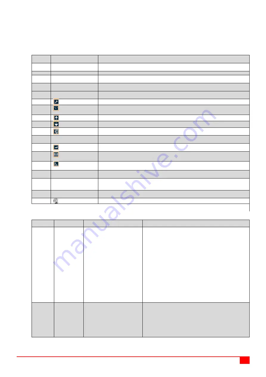
Interface symbols, indicator lights and key descriptions of 2,000 A (and above) shell frame 3H
(liquid crystal) intelligent controller
Serial
number
Symbol/Name
Definition
1
Reset button
After the release is interrupted due to the circuit breaker fault, it is required to press this button before
the circuit breaker can be closed again
2
In
Circuit breaker rated current
3
Liquid crystal display (LCD)
Display all measurement parameters, system setting parameters, protection setting parameters and
all information in Chinese
4
Overload and short-circuit
protection area
When the current protection is set, the indicator light of this area is always on, indicating that the
protection current value or delay time value of the corresponding area is being set;
5
Grounding protection area
In case of fault or alarm, the indicator light of this area flashes, indicating that the corresponding area
is in fault protection or alarm;
6
"System Settings" key
Quickly switch to the "System Settings" main menu ("Right Arrow" when adjusting the system clock)
7
"Running Parameters"
key
Quickly switch to the "Running Parameters" main menu ("Left Arrow" when adjusting the system
clock)
8
"Up Arrow" key
Move the cursor up, change the selected parameter up, or position the display to the left
9
"Down Arrow" key
Move the cursor down, change the selected parameter down, or position the display to the right
10
"Exit" key
Exit the current menu to enter the previous menu, or cancel the modification of the current
parameters
11
Test interface
It has three functions: DC 24 V power input port, analog signal input port, programming and
communication interface
12
"Enter" key
Enter the next menu of the item pointed by the current cursor, select the current parameter, or save
the modification
13
"Information Inquiry"
key
Quickly switch to the "Information Inquiry" main menu
14
"Protection Settings"
key
Quickly switch to the "Protection Settings" main menu
15
“Communication” indicator
light
The communication indicator light is on, indicating that communication data is transmitted; the light
goes off when there is no communication data transmission.
16
"Normal" indicator light
After the controller is powered on, the "Normal" indicator light keeps flashing. If the light does not turn
on after power-on, the intelligent controller is not working properly and shall be replaced
immediately.
17
"Fault/Alarm" indicator light
During normal operation, the fault or alarm indicator light is not on; when the "Fault/Alarm" indicator
light flashes, there must be a fault in the system.
18
"Reset" key
Reset to enter the reset (running) state in a fault trip or an alarm state
Note: Due to the rapid upgrade of the intelligent controller, its physical interface may be different from the existing instruction. Please refer to the
physical object.
6.3
Function configuration table of the intelligent controller
Controller
type
DIP type (L)
Digital type (M)
Liquid crystal type (M, H)
Standard
functions
● Long time
delay protection
● Short-circuit
instantaneous
protection
● Parameter
setting
● Indicator light
display
● Fault
self-diagnosis
● Fault memory
● Thermal
memory
● Test trip
● Long time delay protection
● Short time delay protection
● Short-circuit instantaneous
protection
● Grounding protection (vector sum
type)
● Parameter setting
● Digital display
● Test trip
● Effective value protection
● Test function
● Fault memory
● Fault self-diagnosis
● Thermal memory
● More protection functions, including
six optional characteristic curves
● Contact wear and mechanical life
indication
● Load monitoring (Mode I)
● Short-circuit instantaneous
protection
● Short time delay fixed time
protection
● Multi-curve short time delay inverse
time protection
● Multi-curve long time delay
protection
● Current imbalance protection
● Grounding protection (vector sum
type)
● Neutral phase protection
● Disconnection self-diagnosis
● Load monitoring (Mode I)
● Undervoltage protection
● Overvoltage protection
● Voltage imbalance protection
● Communication function (Type H)
● Thermal memory
● Three-/four-phase current
● Asymmetric grounding current
● Long time delay heat capacity
● Phase & Line voltage
● Voltage imbalance
● Frequency
● Phase sequence
● Power
● Power factor
● Current waveform
● Harmonic influence
coefficient of power grid
● Chinese graphic liquid crystal
display
● LED status indication
● Keyboard operation
● Eight fault records
● Eight alarm records
● Eight shift records
● Main contact wear equivalent
● Number of operations
● Number of trips
● System clock
● Test & Lock
● Fault self-diagnosis
Optional
functions
● Short time
delay protection
● Grounding
protection (vector
sum type)
● Alarm signal
output
● Contact output of four groups of
signals
● MCR and HSISC protection
● Menu functions
Measurement: Voltage, frequency,
power factor, active power, active watt
hour
● Power grid parameter history
recording
● Output of four groups of contacts
● Leakage protection (with special
transformer)
Note: No grounding protection is
required when provided with leakage
protection
● Demand value measurement and
protection
● Temperature control monitoring and
protection
● Zone selective interlock
● Overfrequency protection
● Phase sequence protection
● Reverse power protection
● Reclosing
● Underfrequency protection
● MCR and HSISC protection


