7
CHANGES AND T YPING ERRORS RESERVED
CHANGES AND T YPING ERRORS RESERVED
CHANGES AND T YPING ERRORS RESERVED
7. c
onTrol
panel
•
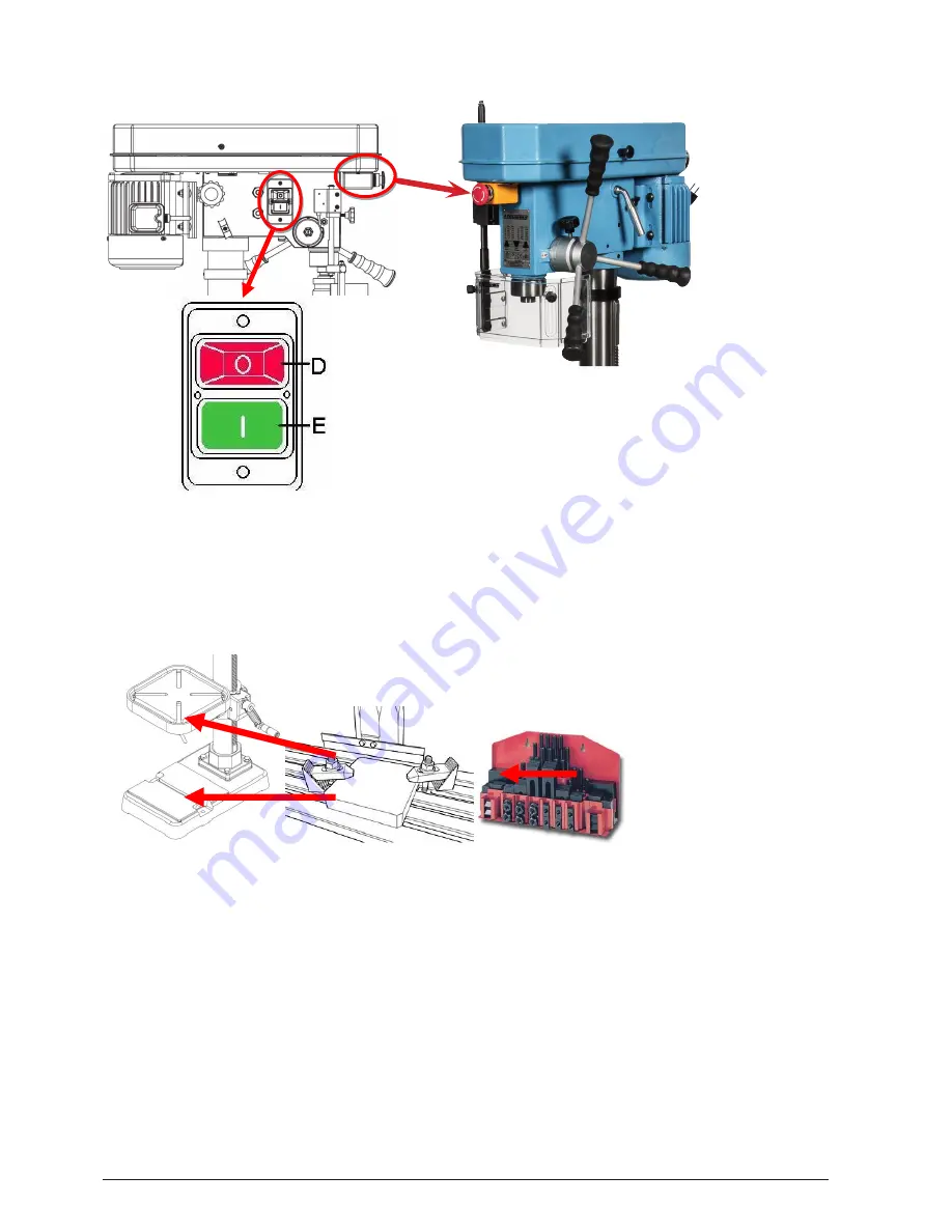
Check the power source. Push the start button to check if the motor and spindle shaft are in normal working
condition.
•
In case of an emergency, push the emergency stop.
7.1 T-
grooves
•
There are T grooves in the worktable and the base. They are used to fix the work piece.
7.2 W
ork
Table
aDjUsTmenT
7.2.1 Height adjustment
•
Loosen the clamp handle on the left hand side.
•
Turn the table handle until the table has reached its proper position.
•
Tighten the clamp handle.
7.2.2
Angle adjustment
•
Loosen the clamp handle on the left hand side.
•
Set the table at the required angle.
•
Tighten the clamp handle.
7.2.3
360
O
Turning
•
Loosen the clamp handle on the left hand side.
•
Turn the table to the desired position.
•
Tighten the clamp handle.
3-2.
Operation illustration and procedure
:
1.
There are three T grooves in the worktable. It is used to fix the work piece.
1-1.There are two T grooves in the base, too. It is convenient for fixing the longer, heavier and larger
working piece.
OPTION
2.
The pulley cover is strictly prohibited to open in normal operation condition.
3.
Protect safety guard shall be allocated in a proper position in operation. It is controlled by a micro
witch. (For CE)
4.
Adjustment of feeding limit
To prevent unwanted penetration to work piece, the feeding limit
shall be set by adjusting the appropriate position of feeding depth
fixing button as long as the distance between the end of tool and
top surface if work piece is measured.
A. Setting of feeding depth
1. Loosen knob A.
2. Turn scaled ring B to desired feeding depth.
3. Lock knob A.
15
Lock
Loose
3-1.
Control panel instruction
:
A.
Emergency Stop Button (For CE)
D.Stop Button
E.Start Button
1.
Check the power source
Push the start button to judge the
motor and spindle shaft is in
normal condition or not.
2.
If it needs to stop urgently, just
push the emergency stop switch.
14
A
A
Figure 6
Figure 7


