7
CHANGES AND T YPING ERRORS RESERVED
7. A
SSEMBLY
S
re A
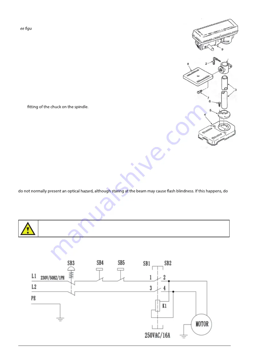
1. Install (3) M8x20 bolts in each hole through column support and base and
tighten with wrench.
2. Slide table support assembly into column.
3. Install support lock handle from left side into table support and tighten by
hand.
4. Lift head assembly above column and slide it onto the column as far as
possible. Align head with table and base. Using a 4 mm hex “L” wrench,
tighten the head lock set screws on the head.
5. Slide the depth stop ring into the hub.
6. Slide the feed handle assembly into the hub and tighten with hex. socket
head cap screws (M8x25).
7. Clean out the tapered hole in the chuck. Clean the spindle nose with a
clean cloth. Push the chuck up on the spindle nose as far as possible.
Lightly tap the nose of the chuck with a piece of wood to ensure proper
8. Choose speed for drilling operation, and install belt to correct position for
desired speed.
9. Loose the screw in the pulley guard (14) and remove the cover (12). Put the
two batteries (11) into the box and the close the cover (12).
10. Tighten the belt and close the pulley guard.
8. L
UBRIFICATION
All of the ball bearing are packed with grease at the factory. They require no further lubrication. Periodically lubricate
the table elevation machanism, the splines (grooves) in the spindle, and the rack (teeth of the quill), see “getting to
know your drill press.”
9. O
PERATION
AND
MAINTENANCE
The laser light/laser radiation used in the machine is class 2 with maximum 1 mW and 400 nm wavelength. These lasers
not perform any operations until normal vision returns.
Frequently blow out any dust that may accumulate inside the motor.
A coat of automotive type paste was applied to the table and column will help to keep the surfaces clean.
Warning
Do not stare directly at the laser beam.
10. W
IRE
DIAGRAM
Frequently blow out any dust that may accumulate inside the motor.
A coat of automotive type paste was applied to the table and column will help to keep the surfaces clean.
Part No.
Component/Object
Manufacturer
PCS
Motor
Motor
AC250V/1PH/400W
1
Lubrication
Wire diagram
All of the BALL BEARING are packed with grease at the factory.They require no further lubrication.
Periodically lubricate the table elevation machanism,the SPLINES (grooves) in the spindle,and the
RACK (teeth of the quill),see "Getting to know your drill press."
Maintenance
Fig. A
1 Base
2 Column/w Support Asm
3 M10*1.5-40 Screw (4)
4 Head asm
5 Table
6 Feed Handle
7 Clamp-Column Lock
8 Crank
Содержание HU 13-2 N
Страница 1: ...HU 13 2 N D R I L L I N G M A C H I N E ...
Страница 5: ...5 LIST OF LOOSE PARTS IN THE BOX AND BAGS ...
Страница 6: ...6 CHANGES AND TYPING ERRORS RESERVED 6 GETTING TO KNOW YOUR DRILL PRESS ...
Страница 9: ...9 CHANGES AND TYPING ERRORS RESERVED 12 EXPLODED DRAWING AND PARTS LIST ...
Страница 12: ...2017 V1 Copyright Huberts BV All rights reserved ...


