DURA
The DURA parameter sets the time duration in minutes for defrost
cycle operation. This time applies to all types of defrosts and acts as a
fail safe time for those defrosts terminated by coil temperature or the
temperature activated switch. In the event that the sensed temperature
of the coil does not reach the preset termination temperature in the
time allotted by this setting, the defrost will terminate and
refrigeration will resume in accordance with the applicable settings
(fan control, master comm. control, etc.)
TTYP
The Safe-NET system is capable of terminating defrost activity based
on evaporator coil temperature (TSEN), return air (RAIR), discharge
air (DAIR), time (TIM) or input from a termination temperature
activated switch (DIGI). When the Safe-NET system is configured to
control defrost, this setting determines which input parameter is used
to terminate a defrost cycle. The DURA setting is always enabled as a
fail-safe defrost duration time in the event a selected termination input
fails. If the failure is such that defrost termination would occur imme-
diately, a 10- minute guaranteed defrost cycle duration is employed.
Note:
The sensed input selected for defrost termination must be installed and
defrost termination set to TSEN for this feature to operate.
STAR
The STAR parameter sets the time of day for the first defrost cycle and
works in conjunction with the NDEF parameter discussed below. This
time setting is for the initial defrost in a 24-hour period. The NDEF
(number of defrosts) determines the number of defrosts that will occur
in a 24-hour period beginning with the STAR (first defrost) parameter.
The maximum number of defrosts allowed in a 24 hour period is 8.
The defrost cycles are spaced evenly across the 24- hour period
beginning with the STAR time. The formula for calculating defrost
start times is as follows:
Defrost interval = 24/NDEF
First defrost cycle start time = STAR
Second start time = STAR + Interval
Third start time = STAR + 2 X Interval
~
Eighth start time = STAR + 7 X Interval
For example, with a STAR value of 01:00 and an NDEF setting of 4
the defrost cycle start times are:
1:00
A
.
M
.
7:00
A
.
M
.
1:00
P
.
M
.
7:00
P
.
M
.
This scheme applies to all types of defrosts.
NDEF
The NDEF parameter sets the number of defrost cycles in a 24-hour
period. This number works in conjunction with the STAR parameter
discussed above. The NDEF (number of defrosts) determines the
number of defrosts that occur in a 24-hour period beginning with the
STAR (first defrost) parameter. The maximum number of defrosts
allowed in a 24 hour period is 8. The defrost cycles are spaced evenly
across the 24- hour period beginning with the STAR time. The formula
for calculating defrost start times is as follows:
Defrost interval = 24/NDEF
First defrost cycle start time = STAR
Second start time = STAR + Interval
Third start time = STAR + 2 X Interval
~
Eighth start time = STAR + 7 X Interval
For example, with a STAR value of 01:00 and an NDEF setting of 4,
the defrost cycle start times are:
1:00
A
.
M
.
7:00
A
.
M
.
1:00
P
.
M
.
7:00
P
.
M
.
This scheme applies to all types of defrosts.
TEMPS MENU
The TEMPS menu is used to display the individual temperatures,
pressures, voltages, current or power factor of connected individual
sensors. The following list shows the order in which the values would
be displayed if all possible sensors were connected. However, the
Safe-NET display module allows only 10 (ten) of the sensors to be
connected simultaneously. At this time, there is no known application
where all 10 sensors or all available sensors would be applied.
The order in which the temps are displayed is dependent upon which
sensing devices are installed, as represented to the right. Missing or
non-connected sensors will not appear in the designated sequence.
Average temperatures are available to view so long as the associated
sensing devices are attached.
DSAV= Discharge Air Average
RTAV=Return Air Average
PDAV=Product Average
T-LO=Lowest Termination Sensor Reading
ILET=Evaporator Inlet
OLET=Evaporator Outlet
TSNL=Left Termination Sensor
TSNC=Center Termination Sensor
TSNR=Right Termination Sensor
DSCL= Discharge Air Left
DSCC=Discharge Air Center
DSCR=Discharge Air Right
RETR= Return Air Right
RETC=Return Air Center
RETL= Return Air Left
PRDR=Product Right
PRDC=Product Center
PRDL=Product Left
ANTI=Anti-sweat Heater temp
PRES-LO=0-200 PSI
TEMP-LO=0-200PSI liquid temp
PRES-HI=0-500 PSI
TEMP-HI=0-500 PSI liquid temp
Controlled load Volts
Controlled load Amps
Controlled Load Power factor
VALVE MENU
The Valve menu is used to configure temperature control output type
and operational parameters for units whose temperature controlling
device (compressor, VSD, liquid solenoid, suction stop solenoid, EEXP,
EEPR) is controlled by the Safe-NET display module. This menu also
contains maintenance functions to allow manual control of a tempera-
ture controlling device for troubleshooting and repair activity.
A relay module properly connected to the compressor contactor,
solenoids, etc., is required for temperature regulating device control
functions. Refer to
Safe-NET Technician’s Manual
, section on
Safe-NET wiring, for proper equipment, techniques and safety
considerations.
Note:
Changing these parameters (as well as performing maintenance
functions) requires that a valid PASSWORD be entered first.
DSVR
The Safe-NET display module software version. The value is not user
changeable so a PASSWORD isn’t needed.
DHVR
Safe-NET display module hardware version. The value is not user
changeable so a PASSWORD isn’t needed.
CLAV
CSVR
CHVR
C-OF
V-OF
NORL
CLOSE
OPEN
SREF
VTYP
This menu item defines the temperature control method applied. This
can consist of electronic evaporator pressure regulating valves, elec-
tronic expansion valves, on/off control of fixed speed compressors,
variable speed drive control of VSD driven compressors, PWM control
of liquid line solenoids and /or suction stop solenoids.
Depending on the temperature control strategy employed, a relay
module properly connected to the compressor contactor, solenoids,
etc., and /or a Safe-NET control module is required for temperature
regulating device control functions. Refer to
Safe-NET Technician’s
Manual
, section on Safe-NET wiring for proper equipment, techniques
and safety considerations.
0-10
CD-16
CD-09
CD-08
ES-20
ES-12
VPOS
NONE
No valve or other temperature control mechanism attached. Safe-NET
used for monitoring purposes only.
CSELF
Safe-NET display module performing ON/OFF control independent of
a Safe-NET control module, but operating under a control module for
defrost coordination. Such applications could include walk-in coolers
with multiple evaporators.
SELF
Safe-NET display module performing ON/OFF control independent of
a Safe-NET control module. The Safe-NET display module can exist on
a network as a sole entity receiving command from a master device.
It controls all functions of the fixture if so equipped (defrost, lighting,
dual-temperature operation, temperature control, alarming, etc.)
OnOff
Safe-NET display module acting as user I/O for a Safe-NET control
module. The Safe- NET display module performs the on/off control
and schedules defrost, case lighting, and evaporator fan control
through the Safe-NET display module control outputs.
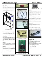
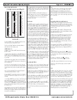
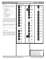
Safe-NET™ Self-contained Operating Instruction
Page
7 of 8 — P/N 0485005_B
www.hussmann.com/cstore/c_techinfo.htm
© 2007 Hussmann Corporation • Bridgeton, Missouri 63044-2483 U.S.A.
20 June 2007
Not applicable for
self-contained units.
Not applicable for
self-contained units.


