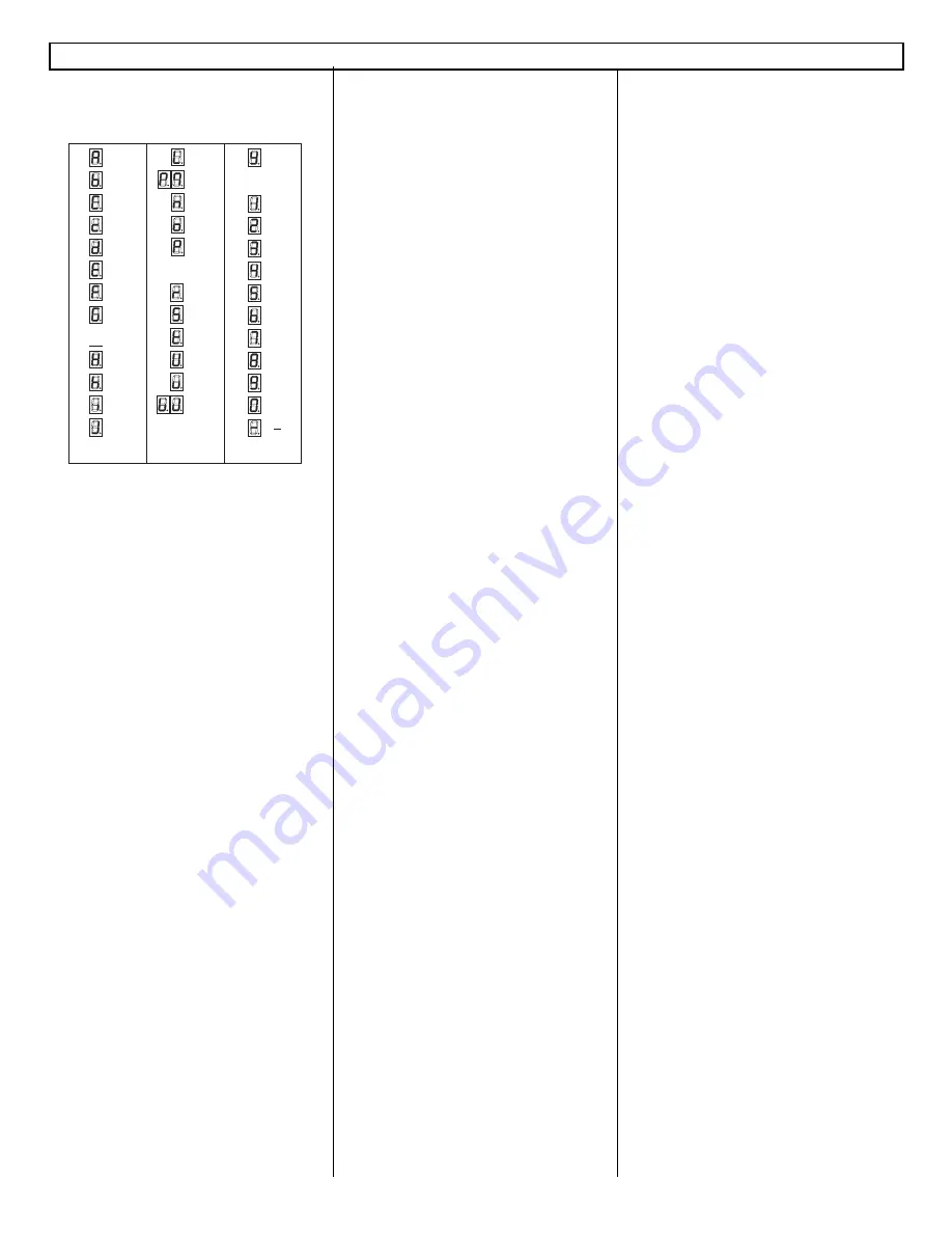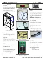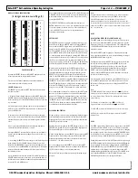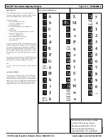
DISPLAY SYMBOL IDENTIFICATION
(A larger version is on Page 8.)
TOP LEVEL MENUS
By using the SELECT button on the Safe-NET display module, the
seven top-level menus can be sequentially accessed.
The seven top-level menus, submenus, actions and definitions are
discussed in detail in the following sections.
SELECT Button Action
The SELECT button on the Safe-NET display module performs two
functions as follows:
1. When the ‘Default Display’is shown on the Safe-NET display, the
SELECT button navigates through the top-level menus in sequence.
Each consecutive press of the SELECT button will advance to the next
top-level menu.
After initial power-up or following a unit reset, navigation begins at
‘dSEt’(set-point), then ‘SETUP’and advances in accordance with the
pattern outlined below.
If the unit reverts to the default display due to either an inactivity
time-out or use of the escape button sequence, pressing the SELECT
button will advance to the next top-level menu in sequence as shown
above.
Once a top-level menu is displayed, the first sub menu item and its
associated value will be displayed after 1 second.
Pressing the SELECT button will move to the next top-level menu in
sequence and the submenu/value cycling will repeat for the new top-
level menu.
2. After using the SELECT button to navigate to the desired top-level
menu, pressing the UP or DOWN button will enter the associated
submenu. If no PASSWORD was previously entered, submenu items
are view-only. If a valid PASSWORD was entered prior to entering the
submenu, editing the submenu items will be allowed as described in
the following sections.
After a submenu has been entered with the UP or DOWN buttons, the
SELECT button functions as an enter key to select submenu items for
modification and to confirm new submenu item values after modifica-
tion via the UP or DOWN buttons.
After a submenu has been entered using the UP or DOWN buttons, the
UP/DOWN buttons become activated to navigate the submenu and to
modify submenu item values when the value of interest is selected by
pressing the SELECT key.
The SELECT / ENTER button will continue functioning as an
ENTER button until a reset occurs, a power up/down sequence occurs,
or an escape sequence is executed. Once any of the aforementioned
occurs, the SELECT button reverts to its original function of
navigating top-level menus.
SETUP MENU
The SETUP menu is used to configure operating parameters of the
Safe-NET system. Enter the SETUP menu by pressing the SELECT
button on the Safe-NET Display module. Once the SETUP menu is
entered, use the UP and DOWN arrows on the Hand-Held device or
the UP and DOWN buttons on the Safe-NET Display module to navi-
gate the SETUP sub-menu. The menu navigates in a circular fashion;
i.e., when the last menu item is displayed, pressing the DOWN arrow
or button will cycle back to the top of the menu. Conversely, pressing
the UP arrow or button when the top menu item is displayed will
navigate to the bottom of the menu. To exit the menu, simultaneously
press the UP and DOWN buttons on the Safe-NET Display module.
When a menu item is displayed, the Safe-NET display will cycle
between the menu item and its current value. To edit the value of the
currently displayed menu item, with the value displayed, press the
SELECT button on the Safe-NET display. The value will begin to
flash. Use the UP/DOWN arrows or buttons to increment/decrement
the selected value. Once the desired value is displayed (flashing), press
the SELECT button on the Safe-NET display to save the value. The
Safe-NET display will revert to cycling between the menu item and its
new value. The UP/DOWN arrows or buttons can now be used to
navigate to any other SET UP menu item to be viewed or modified.
After certain parameter changes are completed, the Safe-NET system
must be reset to initiate operation in accordance with the modified
parameter(s). This may be accomplished in one of two ways. Either
navigate to the RESET sub menu item in the SETUP menu and press
the SELECT button on the Safe-NET display,
OR
cycle power to the
Safe-NET system. Parameter changes requiring a RESET are noted
accordingly in the detailed parameter descriptions.
PASSWORD PROTECTION
Parameters that are critical to proper equipment performance cannot
be modified until a numeric password is entered into the Safe-NET
display module. This prevents accidental or malicious changes in the
Safe-NET system from occurring.
Entering the password is done in the SETUP menu. At the top of the
SETUP menu, press the UP button on the Safe-NET display module.
The display will begin to cycle between PASS and 0.
While 0 is being displayed, press the SELECT button on the Safe-NET
display module to allow editing of the value. With the Safe-NET
display module flashing 0, increment or decrement the value until
it reaches 595. 595 is the password value.
Once 595 is displayed, press the SELECT button on the Safe-NET
display module. The display will revert to cycling between PASS and
595. This enables editing of critical system parameters.
The user may now navigate the menu system and edit parameters as
necessary.
Note:
The password protected access remains active for 5 minutes. Each time
a new parameter is entered by pressing the SELECT button on the
Safe-NET display module, the 5 minute timer is restarted. After 5
minutes with no parameter entries, the password value reverts to 0 and
the password entry process must be performed to regain access to critical
parameters. The SETUP menu can be navigated without a valid password
in a “view only” mode.
DSET
(FIRST OPTION WHEN THE CASE IS TURNED ON.)
The DSET parameter sets the discharge air set point. This set point is
the control point when the Safe-NET system is configured to provide
temperature control of the refrigerated fixture. The configurable range
of the HIGH and LOW alarm set points is centered around this
parameter’s settings.
When the Safe-NET system is applied as a temperature monitoring
device only, this set point has no effect other than limiting the range of
the HIGH and LOW alarm set points.
The display will cycle between DSET and the current set point. While
the set point is being displayed, press the SELECT button on the
Safe-NET display module to allow editing of the value. When the
Safe-NET display module begins flashing the value, use the UP or
DOWN arrow keys on the Hand-Held device or the UP /DOWN
buttons on the Safe-NET display module to increment or decrement
the value to the desired set point.
Once the desired set point is displayed, press the SELECT button on
the Safe-NET display module to store the new value to non-volatile
(NV) memory. The display will revert to cycling between DSET and
the new value.
Note:
The HIGH and LOW alarm settings are limited to +/–
– 16 deg F from
discharge air set point. Setting the discharge air set point will not modify
the current alarm settings. They must be set independently to ensure
proper alarming.
The discharge air set point has a range of –
–55 to +170 deg F.
Proper performance is not guaranteed outside –
–40 to +50 deg F.
The Safe-NET system must be RESET for the new value to take effect .
DSET may be selected as the default display item for the Safe-NET
display module.
PSEN
The PSEN option enables / disables password protection for the DSET
parameter and allows the TOD clock to be set. This may be desirable
when employees or service personnel must have the option of changing
the operating set point of the refrigerated fixture. While PSEN allows
easy modification of the operating set point and TOD clock, no other
operational settings can be modified without entering a password.
Setting this parameter is done in the SETUP menu. After navigating to
the PSEN sub menu item, the display will cycle between PSEN and the
current setting. While the setting is being displayed, press ENTER on
the Hand-Held device or press the SELECT button on the Safe-NET
display module to allow editing of the value. When the Safe-NET
display module begins flashing the value, use the UP or DOWN arrow
keys on the Hand-Held device or the UP /DOWN buttons on the
Safe-NET display module to step through the selections.
Safe-NET™ Self-contained Operating Instruction
Page
4 of 8 — P/N 0485005_B
© 2007 Hussmann Corporation • Bridgeton, Missouri 63044-2483 U.S.A.
www.hussmann.com/cstore/c_techinfo.htm
20 June 2007
L
M
n
o
P
q
r
S
t
U
v
W
w
x
A
b
C
c
d
E
F
G
g
H
h
i
J
k
Not
Used
Not
Used
Not
Used
Not
Used
Not
Used
Not
Used
y
z
1
2
3
4
5
6
7
8
9
0


