background image

REFRIGERANT

The correct type of refrigerant will be stamped
on each merchandiser’s serial plate. The case
refrigeration piping is pressurized, leak tested
and factory sealed. Before making refrigeration
hookups, depress universal line valve to ensure
that coils have maintained pressure during 
shipment.

REFRIGERANT PIPING

Connection Location

The refrigerant line outlets are located under the
fixture towards the center (refer plan view ).
Insulate suction lines to prevent condensation
drippage on the floor.

Line Sizing

Refrigerant lines should be sized as shown on
the refrigeration legend that is furnished for the
store or according to ASHRAE guidelines. 

Refer to data sheet included with this manual for
specific information on the case you are installing. 

Oil Traps

P-traps (oil traps) must be installed at the base of
all suction line vertical risers. 

Pressure Drop

Pressure drop can rob the system of capacity. To
keep the pressure drop to a minimum, keep the
refrigerant line run as short as possible using a
minimum number of elbows. Where elbows are
required, 

USE LONG RADIUS ELBOWS ONLY

.

INSULATION

The suction and liquid lines should be clamped
or taped together and insulated for a minimum of
30 feet from the merchandiser. Additional insula-
tion for the balance of the liquid and suction lines
is recommended wherever condensation drippage
is objectionable or lines are exposed to ambient
conditions.

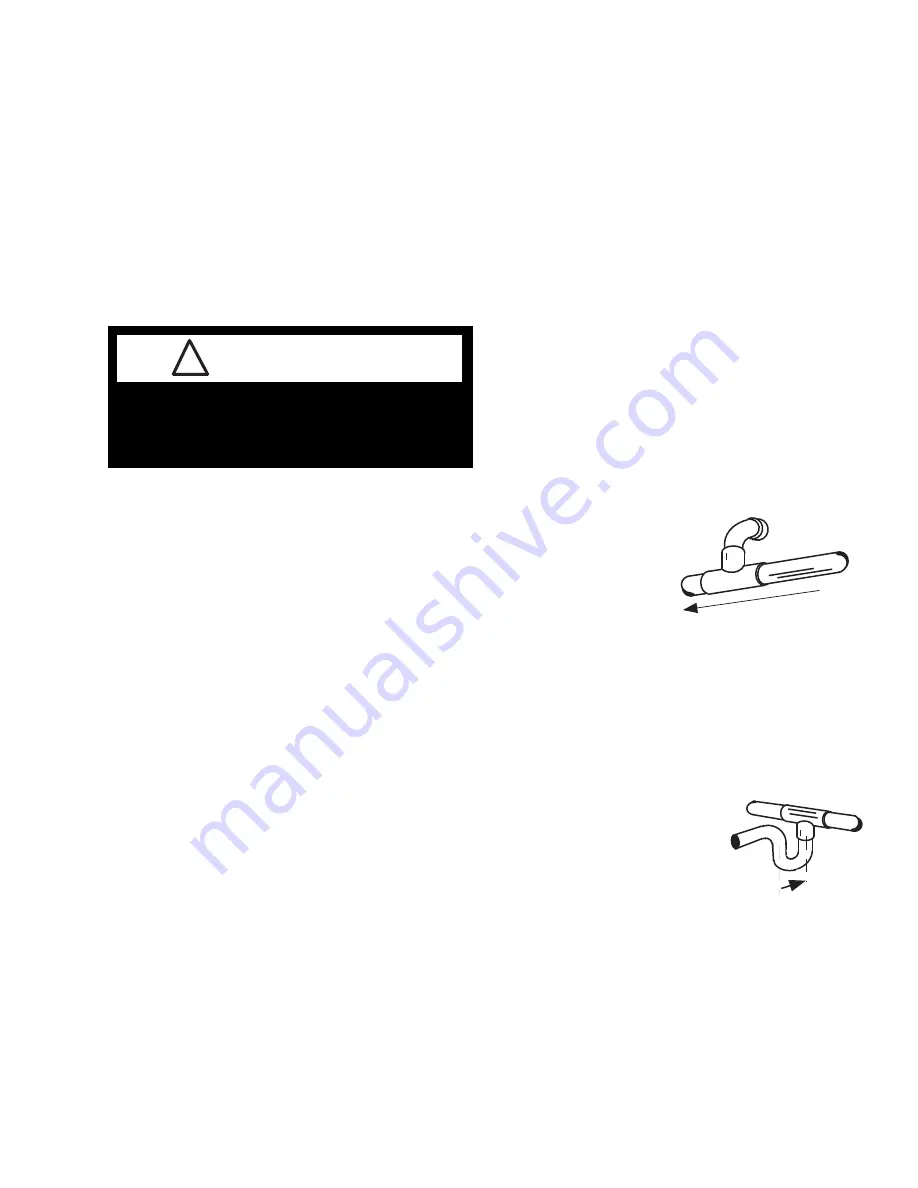
SUCTION LINE

• Pitch in direction of flow.
• May be reduced by one size at one third of case

run load and again after the second third. Do
not reduce below the case suction line size.

• Case suction lines

should enter at the
top of the branch
line.

LIQUID LINE

• May be reduced by one size after one half the

case run load. Do not reduce below the case
liquid line connection size.

• Take-offs to case liquid lines should exit the

bottom of the
branch liquid
line. Provide an
expansion loop
for each evapo-
rator take-off.
(Minimum 3 in.
(76 mm) loop.)

REFRIGERATION / ELECTRICAL

Refrigeration lines are under pressure and

should be depressurized before attempting to

make any connections.

WARNING

!

Island & Multi-deck Island

HUSSMANN CORPORATION • BRIDGETON, MO 63044-2483 U.S.A.

P/N 0446551_A

2-1

Suction Line Return 

Minimum Loop

3-in.  (76 mm) 

Liquid Line Take Off

Содержание RI1

Страница 1: ...SI Remote Models Installation Operation Manual Shipped With Case Data Sheets P N 0446551_A October 2006 I IM M P P O O R R T TA A N N T T K K e ee ep p i in n s st to or re e f fo or r f fu ut tu ur re e r re ef fe er re en nc ce e Merchandisers ...

Страница 2: ... 3 1 Installing Drip Piping 3 1 Installing Splashguards 3 2 Sealing Splashguard to Floor 3 2 START UP OPERATION Start Up 4 1 Stocking 4 1 Load Limits 4 2 Load Limit Profile 4 2 Installing Lighted Shelves 4 4 Installing FDA NSF Required Thermometer 4 6 MAINTENANCE Care and Cleaning 5 1 Plexiglass and Acrylic Care 5 2 Cleaning Mirrors 5 2 Cleaning Center Air Discharge CAD Tower 5 3 Cleaning Honeycom...

Страница 3: ...orms Separately packaged accessories such as kits and shelves should be carefully unpacked Check for damage before discarding packaging Apparent Loss Or Damage If there is an obvious loss or damage it must be noted on the freight bill or express receipt and signed by the carrier s agent otherwise carrier may refuse claim Concealed Loss Or Damage When loss or damage is not apparent until after equi...

Страница 4: ...d and center cases The sectional construction of models 16 ft 4877 mm or longer enables them to be shipped in two sections and to be re joined easily at the job site Some models 16 ft 4877 mm or less are shipped as one section and are not re joined A JOINT TRIM KIT is supplied when appropriate to cosmetically mask the sectional joints This involves applying a vinyl strip to the top of the center a...

Страница 5: ...el from front to back and side to side on inside bulkheads at joint Do not place levels on display pans or on shelves Do not use bolts to draw cases tight Damage may occur 8 Make sure cases are tight and bolted together in all places see diagram Remove clamps 9 Split or end cases such as RIE and SIE have an interlock system built into the CAD tower Joining involves a number of bolts dependent on t...

Страница 6: ...both sides front and back Tape is to protect plexiglass from cement spill over Scarring will occur if cement touches clear plexiglass 2 Separate front plexiglass pieces enough to apply a bead of 40 cement down one edge inside of seam and plastic rod area 3 Apply cement with applicator to one or both surfaces Join immediately 4 Realign front plexiglass and push together tightly Insert the plastic r...

Страница 7: ...ng electrical and refrigeration work has been completed install the splashguards Splashguards may be sealed to the floor using a vinyl cove base trim The size of trim needed will depend on how much the floor is out of level Note that the splashguard must be removable to access components behind it 1 Remove all dirt and wax etc from the area of the splashguard to ensure a secure adhesion 2 Apply a ...

Страница 8: ...number of elbows Where elbows are required USE LONG RADIUS ELBOWS ONLY INSULATION The suction and liquid lines should be clamped or taped together and insulated for a minimum of 30 feet from the merchandiser Additional insula tion for the balance of the liquid and suction lines is recommended wherever condensation drippage is objectionable or lines are exposed to ambient conditions SUCTION LINE Pi...

Страница 9: ...ost cycles for proper operation Refer to the data sheets for application data The Time Clock initiates defrost The evaporator fans continue to circulate air across the evapora tor coil melting any frost build up Defrost can be terminated by either time or temperature Time Termination Standard Should be used for the following types of instal lations 1 Parallel systems with thermostat and liquid sol...

Страница 10: ...ase THERMOSTATIC EXPANSION VALVE ADJUSTMENT Thermostatic expansion valves must be adjusted to fully feed the evaporator Before attempting any adjustments make sure the evaporator is either clear or very lightly covered with frost and that the fixture is within 10 F of its expected operating temperature MEASURE OPERATING SUPERHEAT 1 Determine the suction pressure with an accu rate pressure gauge at...

Страница 11: ...is required for defrost termination thermostats and for optional refrigeration ther mostats When multiple merchandisers are on the same defrost circuit the defrost termination ther mostats are wired in series ALWAYS CHECK THE SERIAL PLATE FOR COMPONENT AMPERES IDENTIFICATION OF WIRING Leads for all electrical circuits are identified by colored plastic bands These bands correspond to the color code...

Страница 12: ...r of the case to allow use of the water seal provided Never use two water seals in series in any one drip pipe DOUBLE WATER SEALS IN SERIES WILL CAUSE AN AIR LOCK AND PREVENT DRAINING 3 Pitch the drip piping in the direction of flow There should be a minimum pitch of 1 8 in per ft 3 mm per 300 mm PVC pipe when used must be supported to maintain the pitch and to prevent warping 4 Avoid long runs of...

Страница 13: ...al sanitation codes or if desired by the customer splashguards may be sealed to the floor using a vinyl cove base trim The size of trim needed will depend on how much the floor is out of level To install the trim to the splashguard 1 Remove all dirt wax and grease from the area of the splashguard where adhesion will be necessary This is to ensure a good and secure installation 2 Apply a good conta...

Страница 14: ...Avoid supplemental flood or spot lighting Factory supplied display lamp intensity is designed for maximum visibility and product life The use of higher output fluorescent lamps H O and V H O will shorten the shelf life of the product From the time the product is received through storage preparation and display the temperature of the product must be controlled to maximize life of the product Keep a...

Страница 15: ...N 0446551_A WWW HUSSMANN COM Load Limit Load Limit Load Limit Load Limit SI3 Optional High Plex with 6 in 152 mm Product Depth Optional Shelves Load Limit Load Limit RI3N Optional High Plex with 6 in 152 mm Product Depth Optional Shelves Load Limit Load Limit RI3 Optional High Plex with 6 in 152 mm Product Depth Optional Shelves LEVITON 13451 20 T8 LAMP 13451 20 T8 LAMP LEVITON T8 LAMP 13451 20 LE...

Страница 16: ...ith 6 in 152 mm Product Depth Optional Shelves Load Limit Load Limit Optional High Plex with 6 in 152 mm Product Depth Load Limit Load Limit RI1N 3 in Space Required Optional High Plex with 6 in 152 mm Product Depth Optional Shelves RI2 Optional High Plex with 6 in 152 mm Product Depth RI1 Load Limit Load Limit 3 in Space Required Optional High Plex with 6 in 152 mm Product Depth SI1 Load Limit Lo...

Страница 17: ...d turned on Verify that the case light switch is turned OFF Switch is located in the canopy on the left behind first row of lamps 5 The illustration below shows a typical case Note that other models will have fewer rows of shelves Starting from the left hand bottom section choose the location for the first shelf X 1 Secure the shelf in the slotted upright Make certain that the shelf is level and t...

Страница 18: ...nstalled as support set the next shelf X 4 in the desired location Remove the cap and insert the shelf plug Continue working left to right installing shelves X 5 and X 6 Note Since the location for the remaining shelves X 4 to X 15 may be directly over the rear wall receptacle the shelf should be plugged in before engaging brackets in the uprights The lower shelf will support the weight of the nex...

Страница 19: ...ck Merchandisers Return Air Grille Shelf Price Tag Molding Suggested Mounting Locations in Single Deck Glass Front Impact Merchandisers Acrylic Package Guard Facing Out Double Stick Tape Flexible Plastic Fits in Price Tag Moldings Thermometer Hussmann P N This is an NSF 7 1999 FDA Food Code Required Thermometer ...

Страница 20: ...located to measure the air temperature in the warmest part of a mechan ically refrigerated unit and in the coolest part of a hot FOOD storage unit B Except as specified in C of this section cold or hot holding EQUIPMENT used for POTENTIALLY HAZARDOUS FOOD shall be designed to include and shall be equipped with at least one integral or permanently affixed TEMPERATURE MEASURING DEVICE that is locate...

Страница 21: ... or any other electrical connection Do Remove the product and all loose debris to avoid clogging the waste outlet Store product in a refrigerated area such as a cooler Remove only as much product as can be taken to the cooler in a timely manner First turn off refrigeration then disconnect electrical power Thoroughly clean all surfaces with soap and hot water DO NOT USE STEAM OR HIGH WATER PRESSURE...

Страница 22: ...tions acrylic parts are dusted with a soft clean cloth to maintain appearance Liquid Anti static coatings should be applied according to manufacturer s directions CLEANING MIRRORS Mirrors are sheets of clear glass that have very thin reflective and protective coatings applied to one side These coatings are susceptible to dete rioration if certain cleaning solutions and even water are allowed to co...

Страница 23: ...ccumulated debris Hussmann recommends this be performed by a trained technician to prevent damage to the coil or electrical components 1 Remove product to cooler 2 DISCONNECT THE ELECTRICAL POWER TO THE MERCHANDISER 3 Remove shelves display racks deck pans CAD gusset and canopy light channel 4 Remove panels attached to CAD tower 5 Verify waste outlets are open and drip piping is not blocked Remove...

Страница 24: ...d remove it from its retainer 4 Clean and dry the honeycomb 5 After cleaning replace in reverse order 6 Turn on power to merchandiser 7 Once operating temperature is reached return product from cooler CLEANING UNDER MERCHANDISERS Remove splashguards not sealed to floor Use a vacuum with a long wand attachment to remove accumulated dust and debris from under the merchandiser REMOVING SCRATCHES FROM...

Страница 25: ... AS INDICATED ON THE PARTS LIST Refer to the case data sheet for each model For access to these fans 1 Turn off power 2 Remove bottom display racks and deck pans 3 Disconnect fan from wiring harness 4 Remove fan blade 5 Lift fan plenum and remove screws holding bottom of motor to fan basket 6 Replace fan motor and blade 7 Lower fan plenum 8 Reconnect fan to wiring harness 9 Turn on power 10 Verify...

Страница 26: ...The ballasts are located in the ballast tray below the case deck The switch in the canopy operates both the canopy and the shelf lamps 1 DISCONNECT POWER TO THE MERCHANDISER 2 Remove the side splashguard and base panels 3 Depending on model the ballasts are in either a hanging ballast box or a slide out ballast try Replace ballast and reassemble parts in reverse order 4 Reconnect the electrical po...

Страница 27: ...n fitting Be sure to drill completely through fitting and bottom liner 2 Apply teflon tape to threaded end of adapter and screw into threaded end of tee 3 Apply an ABS and PVC compatible primer and sealer to adapter and inside of drain Insert adapter into drain fitting Drain Fitting Viewed from Inside Merchandiser Foam Bottom Assembly Modified Drain Fitting PVC Adapter 11 2 x 11 4 inch 38 x 32 mm ...

Страница 28: ...5 3414 X Ergon 1570 E Northgate P O Box 2102 Irving TX 75062 Phone 1 800 527 9916 NOTE Hussmann Aluminum melts at 1125 F 607 C Aladdin 3 in 1 rod at 732 F 389 C X Ergon Acid core at 455 F 235 C Technique 1 Locate Leak 2 REMOVE ALL PRESSURE 3 Brush area UNDER HEAT 4 Use PRESTOLITE TORCH ONLY NUMBER 6 TIP 5 Maintain separate set of stainless steel brushes and USE ONLY ON ALUMINUM 6 Tin surface aroun...

Страница 29: ...ty information or other support contact your Hussmann representative Please include the model and serial number of the product Hussmann Corporation Corporate Headquarters Bridgeton Missouri U S A 63044 2483 01 July 2005 ...

Отзывы: