background image

28

CUTTING UNIT – Cut-n-Break

18

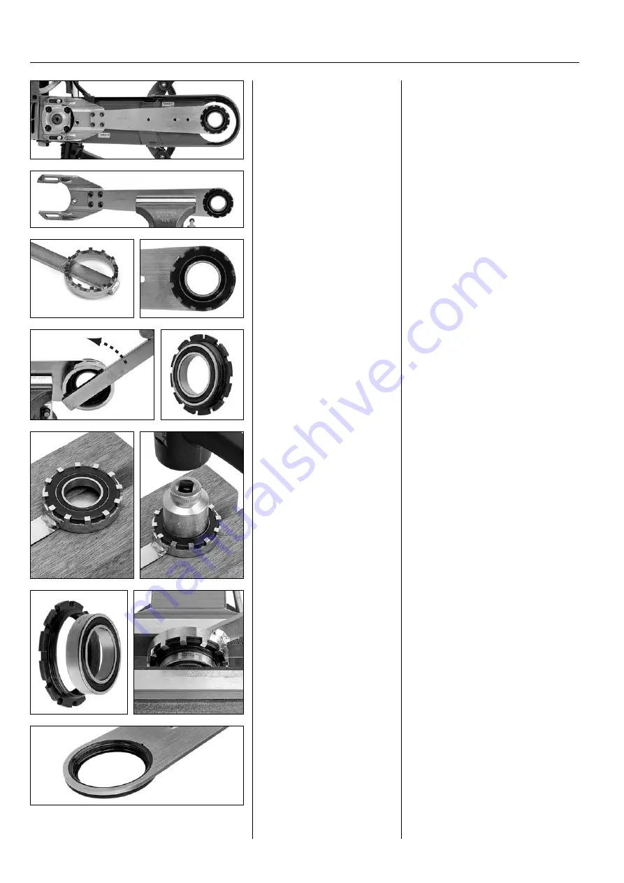
Fit the bearing

The bearing is best fitted by pressing. 
Apply press force to the bearing's outer
ring. 

Alternatively you can fit the bearing
using a vice as shown in the illustration.
Place the bearing holder in the special
tool to give the bearing holder good
support all around.

Fit the bearing

The bearing is best fitted by
pressing. 

Alternatively you can fit the 
bearing using a vice. Place the
bearing holder in the special
tool.

Tools

The special tool 502 53 15-01 is needed
for removal which is used to remove and
fit the threaded bearing holder.

Attach the cutting arm in a vice.

Attach the cutting arm.

Remove the bearing holder

Remove the bearing holder using tool
502 53 15-01. The bearing holder has a
fine thread.

Remove the bearing

Also use the special tool to press the bea-
ring out of the holder. Support the tool
ring with a pair of wood blocks as shown
in the illustration. Press or knock out the
bearing using a suitable socket.

Tools

The special tool 502 53 15-01 is
needed for removal.

Bearing replacement

The cutting arm, where the bearing is
fitted, is now accessible when the belt
guards are removed. See the “Belt replace-
ment” chapter where this work is 
described.

Bearing replacement

Remove the belt guards.

Remove the bearing holder

Remove the bearing holder
using tool 502 53 15-01.

Remove the fixed bearing
holder

The bearing holder in the cutting
arm is positioned with a force
fit. 

The following method for

removal works:

Remove the bearing

Support the tool ring as shown
in the illustration. Press or
knock out the bearing using a
suitable socket.

502 53 15-01

Remove the fixed bearing holder

The bearing holder in the cutting arm is
positioned with a force fit. It is difficult
to remove as there is no chance of achie-
ving a good counter hold

The following method works:

Содержание K 3000-Cut-n-Break

Страница 1: ...HUSQVARNA CONSTRUCTION PRODUCTS Workshop manual K 3000 Electric Wet Cut n Break ...

Страница 2: ... 9 8 TESTING ELECTRICAL COMPONENTS 10 9 ELECTRICAL CABLES CONTACTS 11 10 ROTOR 12 11 ROTOR REPLACEMENT 13 12 STATOR 230 V 14 13 STATOR 120 V 15 14 STATOR REPLACEMENT 16 15 GEAR HOUSING Electric Wet 17 16 GEAR HOUSING Cut n Break 21 17 CUTTING UNIT Electric Wet 24 18 CUTTING UNIT Cut n Break 26 19 WET SYSTEM 31 20 TOOLS 33 CONTENTS Page 2 115 24 59 26 HUSQVARNA K 3000 ...

Страница 3: ...lumn is a more detailed descrip tion and is intended for mechanics with less experience of repair work for this type of machine Contents The manual is divided into numbered chapters as well as chapter headings that are specified in bold at the top of each page The list of contents also has page references to the start of each chapter Spares Spares K3000 The folders include all spares for Husqvarna...

Страница 4: ...t breaker 9 Rotation lock 10 Earth fault breaker 11 Water coupling with valve not Electric K3000 Cut n Break 1 Cutting blades 2 Blade guard 3 Splash guard 4 Water valve 5 Front handle 6 Inspection cover for carbon brushes 7 Starter lock 8 Rear handle 9 Circuit breaker 10 Earth fault breaker 11 Water coupling 12 Belt tensioner 13 Lock nuts for belt adjustment 3 1 2 1 2 5 4 6 7 8 6 7 8 11 9 10 5 6 9...

Страница 5: ...is identical to the K3000 Electric but the blade guard has a wet cutting attach ment with spray nozzles on both sides of the blade 350 mm cutting blade K3000 Husqvarna s electrically driven power cutters are based on a common motor unit that allows wet cutting with a limited amount of water The machine versions are shown in the illustration below The workshop manual deals with the motor unit in a ...

Страница 6: ...es are wear parts that must be checked regularly every week if the machine is used daily You should replace the carbon brushes when around half is left You can easily measure this using a slide gauge without removing the brushes Replace the carbon brushes when the distance from the brush holder to the top level of the brush exceeds 10 mm 4 in Worn carbon brushes checking The importance of replacin...

Страница 7: ...the handle Pull the circuit board from the handle Remove the switch Remove right handle Remove the inspection cover to the car bon brushes as per previous chapter Remove the screws as per the illustration and take off the handle half Remove right handle Remove the inspection cover to the carbon brushes Remove the screws as shown in the illustration 7 CARBON BRUSH HOLDER 5 Replacing the carbon brus...

Страница 8: ... windings b Earth connector from mains cable c Screw for earth connection d Earth connector from earth point to circuit board e Outgoing from switch Illustration 3 f Incoming earthed mains cable g Incoming cables to switch Illustration 4 The illustration shows the attachment of the circuit breaker cables black and white The dashed line shows the routing for the cables between the circuit board and...

Страница 9: ...ition of the components and cables in the handle Illustration 2 a Incoming from mains current b From switch to circuit board c Screw for earth connection and earth connector d From circuit board to stator winding e From circuit board to right connec tion for the carbon brush see illustration 3 position f Illustration 3 The illustration shows the position and attachment of the cables in the handle ...

Страница 10: ...eplaced Earth fault breaker function The earth fault breaker s principle function is fairly simple The current that comes in through the phase conductor must also pass the 0 conductor unless the current takes other routes e g creeping current that is carried on to the earth conductor The conductors run through a coil and if the same current goes in the opposite direction no current is generated in...

Страница 11: ...he measurement on the other pin connection point arrows Check in a similar way that the earth cable is intact Cable earth fault breaker switch Measure between the earth fault breaker s contact points and both switch connec tions Check that the earth cable is intact The earth cable connections are located under the circuit board Cable earth fault breaker switch Check that the earth cable is intact ...

Страница 12: ...cial attention therefore to the differences in the values during the test rather than the absolute values Major differences indicate a defective rotor Rotor assembly The gear housing and motor unit of both machines are designed according to the same principle Four long screws link the motor unit with the gear housing Two screws are reached from the gear housing and two from the rear of the motor T...

Страница 13: ...Removing the blade guard see page 24 K3000 Cut n Break Removing the cutting unit and handle unit see page 30 Divide the gear and motor housing Lift the carbon brushes and lock with the spring Turn the machine with the gear housing down and knocking a few times against the bearing to divide the motor and gear housing Pull the circuit board from the guide slots in the handle Remove the switch by fir...

Страница 14: ... for the carbon brushes and right handle half see Wiring diagram cabling chapter page 8 The stator winding is divided at the circuit board and is connected in the following way Pull out the contacts to the stator at the circuit board Connect the contacts using a cable fitted with flat pin contacts Preparations illustration 2 You do not need to remove the carbon brushes Lift these up and lock with ...

Страница 15: ...ion 1 Remove the inspection cover to the carbon brushes Break the electric circuit to the rotor by pulling out both the carbon brushes a little and lock with the spring to the side Connect one of the test pins to the carbon brush s cable on the left side Disconnect the contact to the stator grey cable at the circuit board and connect to the other test pin Measured values Typical measured values fo...

Страница 16: ...e motor housing Pull the rotor out of the motor housing Pull the circuit board from the guide slots in the handle Remove the switch by first pulling it out wards from the attachment in the bracket and then move it backwards from the handle Pull the circuit board from the handle Remove the switch Remove right handle Remove the inspection cover to the car bon brushes as per previous chapter Remove t...

Страница 17: ...e pulled off the shaft by hand Turn the nut correctly When refitting note that the nut is not symmetrical Turn the side with the shoulder to the drive pinion Later designs have a nut with shoulder on both sides Gear housing and cover after removal Grease missing in the illustration For the sake of clarity the grease that fills most of the gear housing has been taken away Gear housing and cover aft...

Страница 18: ...er each bearing surrounded by washers on both sides Replace felt seal when replacing bearing Remove the bearing Remove the ball bearing using a counter stay device Heating around the bearing seat reduces the press force con siderably Felt seal There is felt seal under each bearing surrounded by washers on both sides Replace felt seal when replacing bearing Remove the circlip Warning wear safety go...

Страница 19: ...t to fit Place the wave spring in place and fit the circlip as far down as possible Press the circlip down in its groove using the tool as shown in the illustration Fit gear housing bearings Fit the tool as per the illustra tions Place a large washer with the nut Pull the bearing in by screwing the nut Fit gear housing bearings Fit the tool as per the illustrations Place a large washer above the n...

Страница 20: ...g Put the socket on the shaft and screw in the screw fitted with nut and washer in the crown gear shaft Hold the screw in place and pull the shaft in by turning the nut Fit the crown gear Use parts of the tool kit 506 37 61 02 and socket 525 30 02 01 Put the socket on the shaft and screw in the screw fitted with nut and washer in the crown gear shaft Pull the shaft in by turning the nut Fit the se...

Страница 21: ...l as it must be re placed in full Replace the drive pinion at the same time Alternative for dismantling The gear housing is accessible for division once the cutting unit has been removed see page 30 Inspection of the crown gear unit and drive pinion as well as re greasing of the bearing housing is possible without removing any more parts Replacement of rotor the front bearing or drive pinion of th...

Страница 22: ...bly Felt seal There is a felt seal under the bearing surrounded by washers on both sides Replace felt seal when replacing bearing Remove the bearing Remove the ball bearing using a counter stay device Heating around the bearing seat reduces the press force considerably Felt seal There is a felt seal under the bearing surrounded by washers on both sides Replace felt seal when replacing bearing Tool...

Страница 23: ...a new gasket and fit the cover with the crown gear Tighten the four screws at a torque of 10 12 Nm Fitting needle bearings Make an assembly tool as per the adjoining illustration Place tape or shrink tubing over the threads Text side upwards Turn the flat side with the text upwards towards the nut Remove the gear housing s needle bearing Use a counter stay device to remove the needle bearing Heati...

Страница 24: ...e screws holds the blade guard to the gear housing and adjusts the gear rings for the blade guard setting Remove the screws Remove the washer Remove the screws Lift out the blade guard Lift off the blade guard Lift up the blade guard from the gear housing The white seal ring releases from the shaft and follows up with the washer under Lift off the blade guard Check that the white plastic seal is i...

Страница 25: ...re engagement when the seal is in the right position Fit the blade guard tighten the screws alter nately Fit the seal ring CUTTING UNIT Electric Wet 17 1 2 3 4 5 6 Centre bushing Fit it this way 1 Add and inner flange washer 2 Insert the centre bushing 3 Fit the screw to attach the cutting blade 4 Press the bushing down by screwing the screw down until it reaches the bottom 5 Remove the screw and ...

Страница 26: ...ith the nut underneath Fit the other with the screw on the top Screw and turn the blade alternately To avoid risking the belt jam ming between the blades they are to be tightened at short intervals while you rotate the blade alternately Remove the blade Press the belt out as far as possible from the centre of the blade Tighten the belt Turn the adjustment washer using a screwdriver or Torx 27 to t...

Страница 27: ...s Fit the belt Apply the belt to the belt guard Fit the front belt guard Fit the front belt guard Fit the four screws Place the spring catches on both sides of the belt guard and fit the fifth screw Fit the belt wheel Belt replacement Fold aside the splash guard Force off the rubber guard from the screw Fold down the splash guard Remove belt guards Remove the screws and nuts as shown in the illust...

Страница 28: ...e bea ring out of the holder Support the tool ring with a pair of wood blocks as shown in the illustration Press or knock out the bearing using a suitable socket Tools The special tool 502 53 15 01 is needed for removal Bearing replacement The cutting arm where the bearing is fitted is now accessible when the belt guards are removed See the Belt replace ment chapter where this work is described Be...

Страница 29: ...ocked into place with a small plastic hammer Removal Add a wooden block under the cutting arm Place the ball bea ring on the bearing holder and knock so that a gap appears bet ween the bearing holder and cutting arm Turn the cutting arm and break up the bearing holder Removal Add a wooden block under the cutting arm right next to the bearing holder Place the ball bearing on the bearing holder and ...

Страница 30: ...og and remove the centre screw Lift off the cutting unit Remove the handle unit Remove the two screws in the shield that hold this against the gear housing Remove both screws at the handle and nut on the underside of the gear housing Remove the handle unit Remove the two screws in the shield Remove both screws at the handle and nut on the under side of the gear housing Separate the units The handl...

Страница 31: ... to how hard the flat surface on the pressure side is exposed to pressure Filter replacement A normal wood screw works excellently as a removal tool for the filter Screw the screw into the filter and pull this out Fit the filter by pressing it in on a flat surface Turn the control correctly The side with a mark and text must be turned to the pressure side that is the side where the water comes in ...

Страница 32: ...screw Remove the spray nozzle Fit the right dimension Check in the spares list that the spray nozzle with the correct dimension is fitted Light tightening Tighten the spray nozzles with moderate force K3000 Wet Construction A spray nozzle is located on each side of the blade guard The water strikes a section of the cutting blade and the centrifugal force carries it out towards the blade s diamond ...

Страница 33: ...nt of blade bearings The tools below can be acquired from Husqvarna Multimeter Make Amprobe 37XR A One of few universal instru ments that can also measure inductance H Henry Check of the electrical system s functions Counter stay device There are a number of manu facturers e g Kukko Germany Snap On USA Removal of bull bearings and needle bearings in gear housing The special tools below are needed ...

Страница 34: ...www husqvarnacp com 115 24 59 26 English 2009 06 ARNE PALMQUIST Print Risbergs ...

Отзывы: