background image

20

 – English

MAINTENANCE

NOTE: Use only HUSQVARNA replacement parts. Use of
other brands of replacement parts can cause damage to your
unit or injury to the operator or others. Your warranty does
not cover damage or liability caused by the use of accessories
and/or attachments not specifically recommended by
HUSQVARNA.

Maintenance schedule

Below you will find some general maintenance instructions.

Daily maintenance

• Check throttle trigger and throttle trigger lockout function.
• Check stop switch function.
• Check that blade/trimmer head does not rotate at idling.
• Clean the exterior of the machine.
• Check that the harness is undamaged.
• Check the guard for damage or cracks.
• Change the guard in case of impacts or cracks.
• Check the trimmer head for cracks and chips or damage.

Replace if necessary.

• A non-balanced blade/trimmer head induces heavy

vibrations that may damage the machine.

• Check that the locking nut is sufficiently tightened.
• Check that nuts and screws are sufficiently tightened.

Weekly maintenance

• Check the starter, especially cord and return spring.
• Clean the carburetor area.
• Clean the exterior of the spark plug.
• Remove it and check the electrode gap.
• Adjust it to 0,5 mm (.020"), or change the spark plug.
• Clean the cooling fins on the cylinder and check that the air

intake at the starter is not clogged.

• Check that the angle gear is filled with grease up to 3/4. Use

special grease.

• Clean the air filter.
• Clean or replace the muffler’s spark arrest screen (only

mufflers with a catalytic converter).

Monthly maintenance

• Clean the fuel tank.
• Clean the exterior of the carburetor and the space around it.
• Clean the fan and the space around it.
• Check fuel hose for cracks or other damage. Change if

necessary.

• Change fuel filter in fuel tank.
• Check clutch, clutch spring and clutch drum for wear.

Change if necessary.

• Check electrical wires and connections.
• Change the spark plug.
• Change the airfilter.
• Check and clean the muffler’s spark arrest screen if necessary

(only mufflers with a catalytic converter).

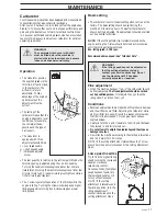
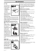
Air filter

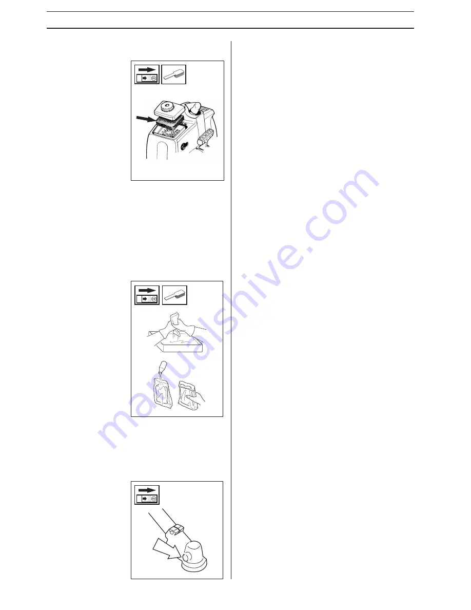
The air filter should be
cleaned regularly removing
dust and dirt to avoid:
• carburetor malfunction
• starting problems
• reduced engine power
• unnecessary wear to

engine parts

• abnormal fuel

consumption

Clean the filter after every
25 hours or more regularly
if operating conditions are
exceptionally dusty.

Cleaning the air filter

Dismantle the air filter cover and remove the air filter. Wash in
clean, warm soapy water. Ensure that the filter is dry before
refitting. An air filter used for a long period of time can never
be cleaned completely. Therefore it is necessary to replace the
filter from time to time with a new filter. A damaged air filter
must always be replaced.

If the machine is used in dusty conditions the air filter
should be soaked in oil, see the section on “

Oiling the air

filter

“.

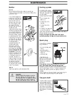
The angle gear is filled with a
sufficient quantity of grease
at the factory. However,
before using the machine you
should check that the angle
gear is filled to 3/4 with
grease. Use special grease.

Normally, the grease does not
need to be changed except
when repairs are carried out.

Angle gear
(322L, 323L, 325L

X

, 325L

XT

, 325LD

X

)

Oiling the air filter

Always use HUSQVARNA
filter oil, order no. 503 47
73-01. The filter oil
contains a solvent to make
it spread evenly through
the filter. You should
therefore avoid skin
contact. Put the filter in a
plastic bag and the pour
the filter oil over it. Knead
the plastic bag to distribute
the oil. Squeeze the excess
oil out of the filter inside
the plastic bag and pour
off the excess before fitting
the filter on the machine. Never use common engine oil. This
would drain through the filter quite quickly and collect in the
bottom.

Содержание 322 L

Страница 1: ...Operator s manual EPA II Please read these instructions carefully and make sure you understand them before using the machine English 322L 323L 325C 325CX SERIES 325LX SERIES 325LXT SERIES 325LDX SERIES ...

Страница 2: ...tput axle rpm This product is in accordance with applicable CE directives Beware of thrown objects and ricochets 50FT 15 m 50FT 15 m Only use non metallic flexible cutting elements that is trimmer head with trimmer cord Use anti slip and stable boots Always wear approved protective gloves Only intended for the trimmer head The operator of the machine shall ensure while working that no persons or a...

Страница 3: ...wo part shaft 19 Air filter 20 Angle gear 20 Maintenance schedule 20 TECHNICAL DATA 322L 323L 21 325LX 21 325LXT 21 325LDX 21 325C 22 325CX 22 EMISSION CONTROL WARRANTY STATEMENT Your warranty rights and obligations 23 Husqvarna AB has a policy of continuous product development and therefore reserves the right to modify the design and appearance of products without prior notice WARNING Under no ci...

Страница 4: ...ved guard fitted See the chapter Technical data If the wrong guard or a defective guard is fitted this can cause serious personal injury MPORTANT INFORMATION A clearing saw brushcutter or trimmer used incorrectly or carelessly can become a dangerous tool that can cause serious or fatal injury to the operator or others It is extremely important that you read and understand the content of this manua...

Страница 5: ...ction Control maintenance and service of the machine s safety equipment WARNING Mufflers fitted with catalytic converters become extremely hot during use and after stopping This also applies at idling speeds Contact can result in burns to the skin Be observant to the risk of fire WARNING Bear in mind that exhaust fumes contain carbon monoxide which can cause carbon monoxide poisoning Therefore nev...

Страница 6: ...ress in the throttle trigger lock and make sure it returns to its original position when released Ensure that the throttle and throttle trigger lock move easily and that their return spring systems function See section Start Start the machine and apply full throttle Release the throttle and check that the cutting equipment stops and remains at a standstill If the cutting equipment rotates with the...

Страница 7: ...achines require a small trimmer head and vice versa This is because when clearing using a cord the engine must throw out the cord radially from the trimmer head and also meet resistance from the grass being cleared The length of the cord is also important A longer cord requires greater engine power than a shorter cord of the same diameter Make sure the knife positioned on the trimmer guard is inta...

Страница 8: ...uipment See the section Personal protective equipment Never use a machine that has been modified so that it no longer corresponds with the original design Never use a machine that is faulty Follow the maintenance control and service instructions in this Operator s Manual Some maintenance and service actions should be carried out by trained and qualified specialists See the chapter Maintenance All ...

Страница 9: ...ure you can walk and stand safely Look out for any obstacles with unexpected movement roots stones branches pits ditches etc Take great care when working on sloping ground 4 The engine should be switched off before moving When moving over longer distances and transporting the transport guard should be used 5 Never put the machine down with the engine running unless you have good sight of it 6 Do n...

Страница 10: ... ground as this can ruin the lawn and damage the tool Do not allow the trimmer head to constantly come into contact with the ground during normal cutting procedures Constant contact can cause damage and wear to the trimmer head Sweeping The rotating cord s fanning effect can be used for quick and easy cleaning Hold the cord parallel to and above the area to be swept and move the trimmer from side ...

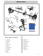
Страница 11: ...Loop handlebar 7 Throttle 8 Stop switch 9 Throttle trigger lock 10 Cylinder cover 11 Starter handle 12 Fuel tank 13 Choke 14 Air purge 15 Air filter cover 16 Clutch cover 17 Handlebar adjustment 18 Locking nut 19 Support flange 20 Drive disc 21 Socket spanner 22 Operator s Manual 23 Allen key 24 Locking pin 25 Shaft coupling ...

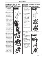
Страница 12: ...the handle on the shaft Note that the handle must be mounted below the arrow on the shaft Fit the bolt securing plate and wing nut as shown in the diagram Tighten the wing nut It is extremely important that the disc drive s support flange s guide engages correctly in the cutting equipment s centre hole when assembling the cutting equipment Cutting equipment assembled incorrectly can result in seri...

Страница 13: ...cure it with the bolt L Fit the drive disc B on the output axle Turn the blade axle until one of the holes in the drive disc aligns with the hole in the gear housing Insert the locking pin C in the hole so that the axle is locked The trimmer head must be split to be fitted see the diagram Proceed as follows Insert your finger into the centre hole of the cover I at the same time as you hold the cov...

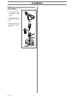
Страница 14: ...ting the spray guard and trimmer head 325CX Fit the guard as shown in the diagram Tighten securely Insert the locking pin into the hole to lock the axle Screw the trimmer head onto the shaft Tighten securely ASSEMBLY ...

Страница 15: ... for water cooled outboard motors so called outboard motor oil Never use oil intended of four stroke engines Clean around the fuel cap Contamination in the tank can disrupt operations Ensure that the fuel is well mixed by shaking the container before filling the tank WARNING The following precautions reduce the risk of fire Do not smoke or place any sources of heat in the vicinity of the fuel Neve...

Страница 16: ... of safety follow these recommendations Check that the support flange is not cracked due to fatigue or due to being tightened too much Discard the support flange if it is cracked Ensure the locking nut has not lost its captive force The nut lock should have a locking force of at least 1 5 Nm The tightening torque of the locking nut should be 35 50 Nm Check that the trimmer head and spray guard are...

Страница 17: ...rating conditions MAINTENANCE Basic setting The carburetor is set to its basic setting when test run at the factory The basic setting should be kept during the machine s first working hours Thereafter the carburetor should be finely adjusted Fine adjustment should be carried out by a skilled technician NOTE If the cutting attachment rotates moves while the engine is idling the T screw should be tu...

Страница 18: ...otate move CAUTION Contact your servicing dealer if the idle speed setting cannot be adjusted so that the cutting attachment stops Do not use the machine until it has been properly adjusted or repaired High speed needle H The high speed needle affects the machine s power speed temperature and fuel consumption A too lean adjustment on the high speed needle H the high speed needle H is screwed in to...

Страница 19: ... screen will cause the engine to overheat resulting in damage to the cylinder and piston Also see under Maintenance NOTE Never use a machine with a defective muffler WARNING Mufflers fitted with catalytic converters become extremely hot during use and after stopping This also applies at idling speeds Contact can result in burns to the skin Be observant to the risk of fire 1 4 3 2 Spark plug The co...

Страница 20: ...ank Check clutch clutch spring and clutch drum for wear Change if necessary Check electrical wires and connections Change the spark plug Change the airfilter Check and clean the muffler s spark arrest screen if necessary only mufflers with a catalytic converter Air filter The air filter should be cleaned regularly removing dust and dirt to avoid carburetor malfunction starting problems reduced eng...

Страница 21: ...nt sound pressure level is calculated as the time weighted energy total for sound pressure levels under various working conditions with the following time distribution 1 2 idle and 1 2 max speed NOTE Sound pressure at the user s ear and vibration on the handles are measured with all the machine s approved cutting equipment fitted The table indicates the highest and lowest values 322L 323L 1 50 24 ...

Страница 22: ...lent sound pressure level at the user s ear measured according to ANSI B175 3 1997 dB A min max Vibration levels Vibration levels on the handles measured according to ANSI B175 3 1997 m s2 When idling left right handles min When idling left right handles max At max speed left right handles min At max speed left right handles max TECHNICAL DATA Note 1 Equivalent sound pressure level is calculated a...

Страница 23: ...93 42 02 Type Tricut 300 mm Trimmy Fix Trimmy HII 1 Trimmy Hit Trimmy Hit Pro Superauto II 1 322L 323L 325LX 325LXT 325LDX 325C Approved accessories Thread blade shaft 3 8 Plastic knives Trimmer head Cutting attachment guard Art No 537 07 67 01 537 07 67 01 537 07 67 01 537 07 67 01 Type Tricut 230 mm R Trimmy Hit VI R Trimmy Fix R Trimmy Hit VII R 325CX Art No 537 19 67 01 537 19 66 01 537 19 69 ...

Страница 24: ... subsequent purchaser that the engine is free from defects in materials and workmanship which cause the failure of a warranted part for a period of two years WHAT IS COVERED REPAIR OR REPLACEMENT OF PARTS Repair or replacement of any warranted part will be performed at no charge to the owner at an approved Husqvarna Forest Garden servicing dealer If you have any questions regarding your warranty r...

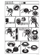
Страница 25: ...English 25 1 Super Auto II Super Auto II 1 2 3 4 5 6 7 8 9 10 4 0 m 13 2 4 mm 095 2 0 m 6 5 6 6 15 cm 15 cm ...

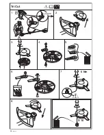
Страница 26: ...26 English 1 Tri Cut 2 3 4 5 6 7 8 20mm 20mm B A 6 Nm X 10 ...

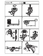
Страница 27: ...English 27 1 Trimmy H II 2 3 4 5 6 7 8 9 7 5 m 25 2 0 2 4 mm 080 095 1 2 15 cm 6 3 7 m 12 15 cm 6 ...

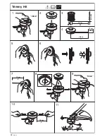
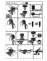
Страница 28: ...28 English 1 Trimmy Hit 2 3 4 5 6 7 8 9 10 11 Click Click 7 0 m 23 12 cm 5 3 5 m 11 15 cm 6 2 0 2 4 mm 080 095 15 cm 6 ...

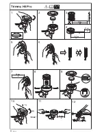
Страница 29: ...English 29 1 Trimmy Hit Junior 2 5 6 7 8 9 10 12 Click 3 4 5 75 m 19 2 0 2 4 mm 080 095 15 cm 6 2 8 m 9 1 2 11 15 cm 6 15 cm 6 ...

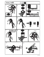
Страница 30: ...30 English 1 Trimmy Hit Pro 2 5 6 7 8 9 10 12 Click 3 4 7 5 m 25 2 0 2 4 mm 080 095 15 cm 6 3 7 m 12 1 2 11 15 cm 6 15 cm 6 ...

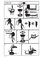
Страница 31: ...English 31 1 Trimmy Hit VI 2 5 6 3 4 7 8 9 10 11 Click 7 0 m 23 12 cm 5 3 5 m 11 15 cm 6 2 0 2 4 mm 080 095 15 cm 6 ...

Страница 32: ...32 English 1 2 3 4 5 6 7 8 9 35 50 NM 15 cm 6 Clic 3 5 m 11 7 0 m 23 2 4 3 3 mm 095 130 12 cm 5 Trimmy SII ...

Страница 33: ...English 33 ...

Страница 34: ...34 English 6 2 1 15 cm 6 7 8 9 10 11 15 cm 1 2 3 4 5 6 7 0 m 23 2 0 mm 080 12 cm 5 3 5 m 11 Trimmy VII H y 5h ...

Страница 35: ...English 35 ...

Страница 36: ...2002W11 H y 5h 114 00 98 95 ...

Отзывы: