4. Pull up the knob and attach the shaft.
8.12 Bevel gear
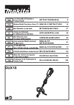
8.12.1 To disassemble the bevel gear
1. Remove the trimmer head (A). Remove the support
flange (Y). Put a rod through the hole (B) to lock the
axle. Remove the protective plate (C). Remove the
screw (D), the screws (E) and the bracket (F).
Remove the screw (G) and the bracket (H). Remove
the screw (I) and pull out the gear housing (J).
D
E
F
H
G
I
A
J
B
C
Y
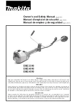
2. Remove the bushing (K). Remove the snap ring (L)
with pliers. Remove the snap ring (M) with pliers.
Remove the grease plug (N).
K
L
N
M
627 - 002 - 23.04.2018
Repair instructions - 49
Содержание 131RB
Страница 1: ...Workshop manual 131RB English 627 002 23 04 2018 ...
Страница 67: ...627 002 23 04 2018 Troubleshooting 67 ...
Страница 68: ...1159786 26 2018 06 25 ...