background image

6

ASSEMBLY / PRE-OPERATION

AUGER

CONTROL 

LEVER

AUGER CONTROL ROD

AUGER

CONTROL 

BRACKET

RETAINER 

SPRING

FIG. 6

CHUTE

ROTATER 

HEAD

3/8 WASHER

3/8 LOCKNUT

THREADED  

STUD

PIN

ROTATER HEAD 

MOUNT ING 

BRACKET

CHUTE 

BRACKET

FIG. 7

ALIGN BEFORE

TIGHTENING LOCKNUT

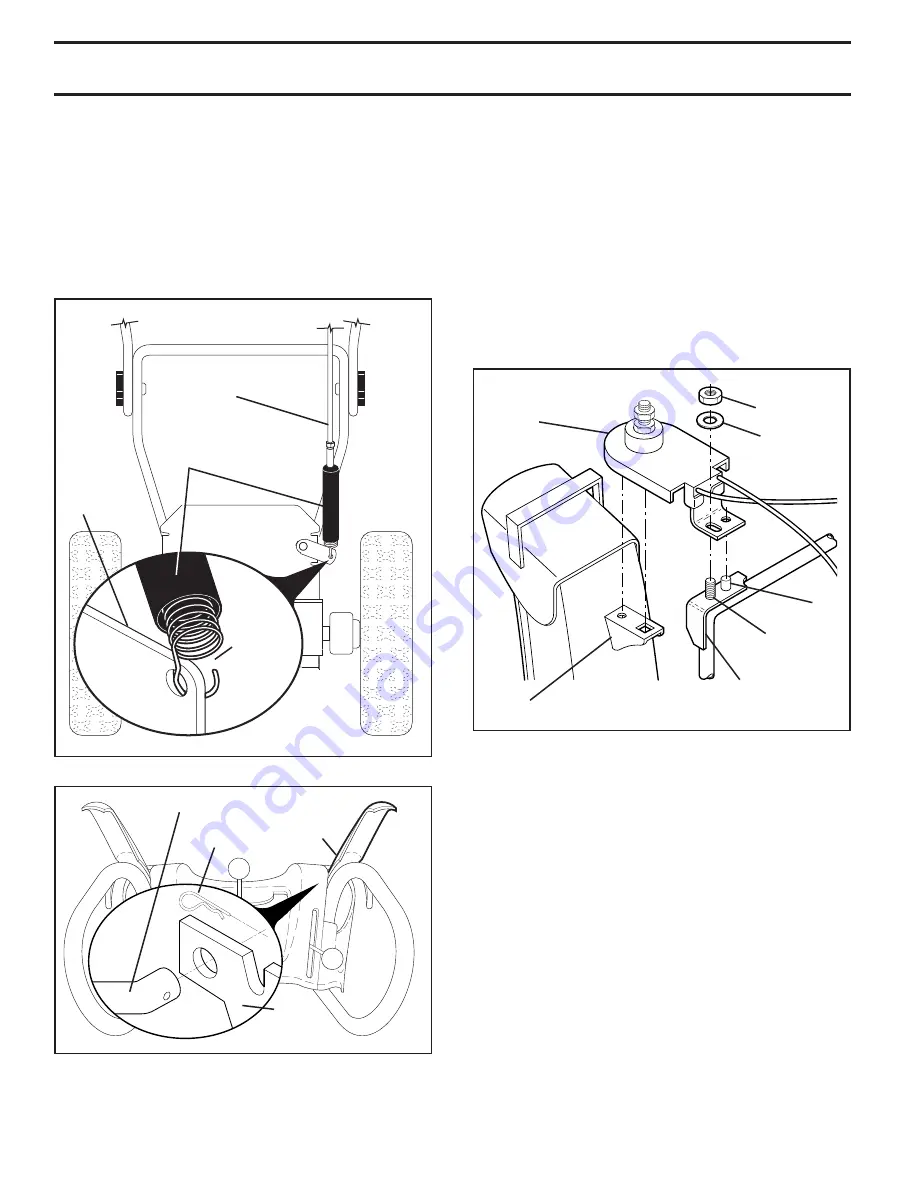
INSTALL AUGER CONTROL ROD (See Figs. 5 and 6)

1.   Retrieve vinyl sleeve and spring from bag of parts and 

retrieve the auger control rod from carton chute tray.  

Slide straight rod end through the small hole in the 

vinyl sleeve. Hook spring in hole in rod end.

2.  Hook end of spring into control arm with loop opening 

up as shown. (See Fig. 5)

3.  With top end of rod positioned under right side of 

control panel, push down on rod and insert end of rod 

into hole in auger control bracket.  Secure with retainer 

spring.

AUGER

CONTROL 

ROD

CONTROL 

ARM

VINYL 

SLEEVE

LOOP 

OPENING 

UP

FIG. 5

INSTALL DISCHARGE CHUTE / CHUTE ROTATOR 

HEAD (See Fig. 7)
NOTE:

 The multi-wrench provided in your parts bag may 

be used to install the chute rotator head.
1.  Place discharge chute assembly on top of chute base 

with discharge opening toward front of snow thrower.

2.  Position chute rotator head over chute bracket.  If nec es-

 sary, rotate chute assembly to align square and pin on un-

 der side of chute rotator head with holes in chute brack et.

3.  With chute rotator head and chute bracket aligned, 

po si tion chute rotator head on pin and threaded stud 

of mounting bracket.

4.  Install 3/8 washer and locknut on threaded stud and 

tighten securely.

CHECK TIRE PRESSURE

The tires on your snow thrower were overinflated at the fac-

tory for shipping purposes.  Correct and equal tire pres sure 

is important for best snow throwing performance.
•  Reduce tire pressure to 14-17 PSI.

Содержание 11527SB

Страница 1: ...11527SB 11527SB Operator s Manual ...

Страница 2: ... the machine Operation 1 Do not put hands or feet near or under rotating parts Keep clear of the discharge opening at all times 2 Exercise extreme caution when operating on or cross ing gravel drives walks or roads Stay alert for hidden hazards or traffic 3 After striking a foreign object stop the engine motor remove the wire from the spark plug disconnect the cord on electric motors thoroughly in...

Страница 3: ...e at high transport speeds on slippery surfaces Look behind and use care when operating in reverse 13 Disengage power to the collector impeller when snow thrower is transported or not in use 14 Use only attachments and accessories approved by the manufacturer of the snow thrower such as wheel weights counterweights or cabs 15 Never operate the snow thrower without good visibility or light Always b...

Страница 4: ...amiliar ize you with the unit which will assist you in assembly operation and maintenance of the product Your new snow thrower has been assembled at the factory with the exception of those parts left unassembled for ship ping purposes All parts such as nuts washers bolts etc necessary to complete the assembly have been placed in the parts bag To ensure safe and proper operation of your snow throwe...

Страница 5: ...ol panel push rod down and insert top end of rod into hole in drive control bracket Secure with retainer spring TRACTION DRIVE CONTROL ROD VINYL SLEEVE FIG 3 PLASTIC TIE NOTE The multi wrench may be used for assembly of the chuterotatorheadtosnowthrowerandmakingadjustments to the skid plates UNFOLD UPPER HANDLE 1 Raise upper handle to the operating position and tighten handle knobs securely Additi...

Страница 6: ...cket Secure with retainer spring AUGER CONTROL ROD CONTROL ARM VINYL SLEEVE LOOP OPENING UP FIG 5 INSTALL DISCHARGE CHUTE CHUTE ROTATOR HEAD See Fig 7 NOTE The multi wrench provided in your parts bag may be used to install the chute rotator head 1 Place discharge chute assembly on top of chute base with discharge opening toward front of snow thrower 2 Positionchuterotatorheadoverchutebracket Ifnec...

Страница 7: ...s Save this manual for future reference These symbols may appear on your snow thrower or in literature supplied with the product Learn and understand their meaning FORWARD PRIMER IGNITION KEY INSERT TO START AND RUN PULL OUT TO STOP READ AND FOLLOW ALL SAFETY INFORMATION AND INSTRUCTIONS BEFORE USE OF THIS PRODUCT KEEP THESE INSTRUCTIONS FOR FUTURE REFERENCE DANGER OR WARNING REVERSE SNOW DISCHARG...

Страница 8: ...t button used for starting the engine Recoil auxiliary starter handle used for starting the engine Primer pumps additional fuel from the carburetor to the cylinder for use when starting a cold engine Choke control used for starting a cold engine MEETS A N S I SAFETY REQUIREMENTS Our snow throwers conform to the standards of the American National Standards Institute TRACTION DRIVE CONTROL LEVER DIS...

Страница 9: ...osition of the chute deflector Set the deflector low to throw snow a short distance set the deflector higher to throw snow farther Tochangethedeflectorposition loosenknob movede flector to desired position and tighten knob securely HIGH POSITION CHUTE DEFLECTOR LOW POSITION KNOB FIG 12 TO CONTROL SNOW DISCHARGE See Figs 11 12 WARNING Snow throwers have ex posed rotating parts which can cause sever...

Страница 10: ...e Fig 14 In certain snow conditions the discharge chute may be come clogged with ice and snow Use the clean out tool to dislodge this blockage When cleaning repairing or inspecting make certain all controls are disengaged and the au ger impellerandallmovingpartshavestopped Disconnect the spark plug wire and keep the wire away from the spark plug to prevent ac cidental starting Releasetheaugercontr...

Страница 11: ...nent damage may occur TO ADJUST SKID PLATES See Fig 16 NOTE The wrench provided in your parts bag may be used to adjust the skid plates Skid plates are located on each side of the auger housing and adjust the clearance between the scraper bar and the ground surface Adjust skid plates evenly to proper height for current surface conditions For removal of snow in normal conditions such as a paved dri...

Страница 12: ... may cause flooding preventing the engine from starting If you do flood the engine wait a few minutes before attempting to start and DO NOT push the primer 5 Pull recoil starter handle quickly Do not allow starter rope to snap back 6 Whentheenginestarts releasetherecoilstarterhandle and slowly move the choke control to the OFF posi tion Allow the engine to warm up for a few minutes Engine will not...

Страница 13: ...hedule in this manual NOTE Use only Original Equipment Manufacturer OEM parts to service this unit Failure to do so can cause the unit to malfunction and pose a risk of injury to the operator BEFORE EACH USE 1 Check engine oil level 2 Check for loose fasteners 3 Checkcontrolstobesuretheyarefunctioningproperly LUBRICATION Keep your snow thrower well lubricated See LUBRICATION CHART SNOW THROWER Alw...

Страница 14: ...annot come in contact with plug 2 Clean area around drain plug 3 Remove drain plug and drain oil in a suitable container 4 Install drain plug and tighten securely 5 Wipe off any spilled oil from snow thrower and engine 6 Install left wheel if removed for draining oil Be sure to install klick pin into proper hole in wheel axle See TO REMOVE WHEELS in the Service and Adjustments section of this manu...

Страница 15: ...rol lever is engaged check to see if the capscrews have sheared To replace the capscrew shear bolts 1 Disengage all controls and move throttle control to STOP position Wait for all moving parts to stop 2 Remove safety ignition key and disconnect spark plug wire from spark plug Place wire where it cannot come in contact with spark plug 3 Align holes in impeller hub with holes in impeller shaft and ...

Страница 16: ...e belt s be replaced by a service center department NOTE It is recommended that both the auger and traction drive belt be replaced at the same time The V belts on your snow thrower are of special construc tion and should be replaced by original equipment manu facturer OEM belts available from your nearest service center department Using other than OEM belts can cause personal injury or damage to t...

Страница 17: ...y turning the adjuster turn buckle located on the right hand cable Grasp the long section tightly and turn the short section to lengthen the adjuster Adjust until cable is snug ADJUSTER TURN BUCKLE FIG 22 ENGINE SEE ENGINE MANUAL CARBURETOR Your carburetor is not adjustable Engine performance should not be affected at altitudes up to 2 134 meters If your engine does not operate properly due to sus...

Страница 18: ... system of an engine while in storage Empty the fuel tank by starting the engine and letting it run until the fuel lines and carburetor are empty Never use engine or carburetor cleaner products in the fuel tank or permanent damage may occur Use fresh fuel next season NOTE Fuel stabilizer is an acceptable alternative in min imizing the formation of fuel gum deposits during storage Add stabilizer to...

Страница 19: ...dles or 1 Choke is in FULL position 1 Move choke to OFF position runs roughly 2 Blockage in fuel line 2 Clean fuel line 3 Stale fuel 3 Empty fuel tank carburetor refill with fresh clean gasoline 4 Water in fuel 4 Empty fuel tank carburetor refill with fresh clean gasoline 5 Carburetor is in need of 5 Contact an authorized service center department adjustment or overhaul Excessive 1 Loose parts or ...

Страница 20: ...nty obligation of the other manufacturer s engines b Transmissions Except where otherwise indicated on Exhibit A Transmission Transaxle including Drive Systems are not covered by this warranty In most cases these items are NOT manufactured by Husqvarna in which case they may be covered separately by their respective manufacturer s warranties if one is provided and included with the product at the ...

Страница 21: ...emoved damaged air filter excessive dirt abrasives salt water moisture corrosion rust varnish stale fuel or any adverse reaction due to incorrect storage procedures n Failures due to improper set up pre delivery service or repair service by anyone other than an authorized Husqvarna servicing dealer during the warranty period o Dirt contaminated grease or oil use of incorrect type of greases or oil...

Страница 22: ...TY Other Non Expendable Components 2 Years NO WARRANTY NO WARRANTY Snow Throwers Engine Residential Zero Turn Mowers MZ EZ Product Component Residential Zero Turn Mowers RZ Only Engine Other Non Expendable Components 2 Years 90 days 90 days Tillers Engine Battery 1 Year Pro rated NO WARRANTY NO WARRANTY Other Non Expendable Components 2 Years NO WARRANTY NO WARRANTY Tiller Tines NO WARRANTY NO WAR...

Страница 23: ...tery 1 Year 1 Year 1 Year P t A i if h d All other Pressure Washers 6027PW 9032PW 1340PW Parts Accessories if purchased Accessories e g grass catcher bumper guard accessories etc 1 Year NO WARRANTY NO WARRANTY Parts e g belts blades etc 30 days NO WARRANTY NO WARRANTY Parts Accessories if replaced in Warranty Service Replacement parts and or accessories provided under this Limited Warranty are war...

Страница 24: ...532 43 58 82 06 23 10 TH Printed in the U S A ...

Отзывы: